Edge material-passing device in ball mill

A technology of feeding device and ball mill, applied in grain processing and other directions, can solve the problems of insufficient grinding of materials, low grinding efficiency, clogging of screen gaps, etc., to achieve uniform feeding and improve grinding quality.

Pending Publication Date: 2018-02-16
YANCHENG JIDA ENVIRONMENTAL PROTECTION EQUIP
View PDF4 Cites 1 Cited by
  • Summary
  • Abstract
  • Description
  • Claims
  • Application Information

AI Technical Summary

Problems solved by technology

[0003] The material enters the first chamber of the mill from the feeding device. After the first chamber achieves coarse grinding, it enters the second chamber through the partition board for further grinding. The partition board is mostly made of fan-shaped boards with a center hole in the middle. The ball mill introduces wind into the cylinder through the fan to promote the flow of materials, but some materials directly enter the next warehouse through the center hole of the partition board under the action of the wind, resulting in insufficient grinding of materials, and at the same time The effective length of the grinding is short and the grinding efficiency is low; some compartments are equipped with sieves, but the length of the sieves is fixed, and the passing rate of the compartments is fixed, which cannot be adjusted according to the input amount of materials and grinding requirements. If the amount of material input is too large and the passing rate of the compartment plate is low, the material is easy to accumulate in the sieve gap, resulting in blockage of the sieve gap, the temperature in the ball mill is too high, and the machine is damaged; if the pass rate of the compartment plate is too high, the material is easy to pass through quickly The partition board enters the next warehouse, resulting in insufficient grinding of materials

Method used


Image

  • Edge material-passing device in ball mill
  • Edge material-passing device in ball mill
  • Edge material-passing device in ball mill

Examples


Embodiment Construction

[0014] The present invention will be further explained below in conjunction with the accompanying drawings and specific embodiments. It should be understood that the following specific embodiments are only used to illustrate the present invention and not to limit the scope of the present invention; it should be noted that the word "before" used in the following description , "rear", "left", "right", "upper" and "lower" refer to directions in the drawings, and the words "inner" and "outer" refer to directions towards or away from the geometric center of a particular part, respectively ;

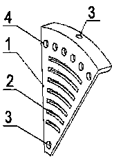
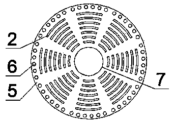
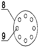
[0015] The present invention provides a kind of material passing device at the inner edge of a ball mill, including a sieve plate 1, a mounting plate 8 and an adjusting plate 5; figure 1 As shown, the sieve plate 1 is a fan-shaped plate, and the sieve plate 1 is provided with a sieve slot 2. The sieve slot 2 is an evenly arranged arc-shaped seam with the same center as the sieve plate 1, and t...


PUM


Abstract

The invention discloses an edge material-passing device in a ball mill. The edge material-passing device in the ball mill comprises a screening plate, a mounting plate and an adjusting plate. The screening plate is a sector plate, screening seams are arranged on the screening plate, mounting holes are formed in the two ends of the screening plate, and adjusting holes are evenly formed in the end,with the larger diameter, of the screening plate; the mounting plate is a circular plate, and a circle of circular holes are evenly formed in the mounting plate; the adjusting plate is a circular plate, an avoiding hole is formed in the center of the circular plate, the diameter of the avoiding hole is equal to the outer diameter of the mounting plate, screening seams are arranged on the adjustingplate, and through holes are evenly formed in the adjusting plate along a circle of the outer edge. The effective lengths of the screening seams in the edge material-passing device in the ball mill can be changed by rotating the adjusting plate, accordingly, the passing rate of the screening plate is changed, the suitable passing rate can be selected for grinding according to the factors such asthe input quantity and the grinding requirements of materials, and the material grinding quality is improved.

Description

technical field [0001] The invention belongs to the technical field of ball mills, in particular to a material passing device for the inner edge of a ball mill. Background technique [0002] The ball mill is the key equipment for crushing the material after it is crushed. The ball mill is composed of a horizontal cylinder, a hollow shaft for feeding and discharging materials, and a grinding head. The cylinder is a long cylinder with grinding bodies inside. The cylinder is a steel plate Manufactured, there is a steel liner and the cylinder is fixed, the grinding body is generally a steel ball, and it is loaded into the cylinder according to different diameters and certain proportions, and the grinding body can also be steel section; the material is loaded into the cylinder by the hollow shaft at the feed end of the ball mill In the body, when the cylinder of the ball mill rotates, the grinding body is attached to the cylinder liner and taken away by the cylinder due to inerti...

Claims


Application Information

Patent Timeline
Patent Type & Authority Applications(China)
IPC IPC(8): B02C17/10B02C17/18B02C23/16
CPCB02C17/10B02C17/18B02C23/16
Inventor 朱顺明
Owner YANCHENG JIDA ENVIRONMENTAL PROTECTION EQUIP
Why Eureka
Try Eureka