Supercharge Your Innovation With Domain-Expert AI Agents!

Mounting for a radar of a vehicle

A mount and radar technology, applied in the radar field, can solve problems such as damage and radar deformation

Active Publication Date: 2018-03-16
RENAULT SA
View PDF5 Cites 6 Cited by
  • Summary
  • Abstract
  • Description
  • Claims
  • Application Information

AI Technical Summary

Problems solved by technology

[0008] Depending on the force of the impact, the radar in a fixed position may be deformed or actually damaged considerably

Method used


Image

  • Mounting for a radar of a vehicle
  • Mounting for a radar of a vehicle

Examples


Embodiment Construction

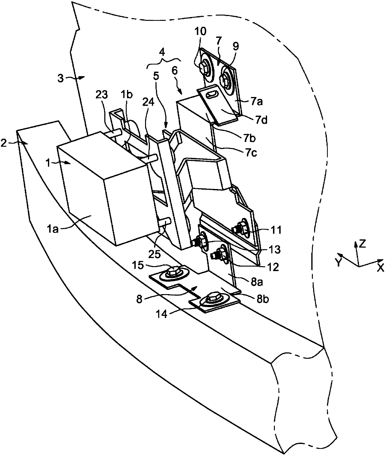
[0041] Such as figure 1 The radar shown in , generally indicated by reference number 1 , is arranged on top of a beam 2 which is arranged at the front of the vehicle 3 . The radar 1 comprises two surfaces 1a and 1b. The face 1 a faces and is arranged in a direction near a sign (not shown in the figure), which is provided on the front of the vehicle 3 . The face 1 b is arranged towards the mount 4 which is attached to the front of the vehicle 3 and to the cross member 2 . The beam emerges from face 1a and opens towards the marking. Radar 1 also includes three arms 23 , 24 and 25 .

[0042] In the example shown, the mount 4 comprises two elements made of sheet metal, a main element 5 extending in the transverse direction, and a receiving element 6 extending vertically.

[0043] Furthermore, receiving element 6 advantageously corresponds to an assembly of two parts 7 and 8 .

[0044] The first part 7 itself may be formed from four parts 7 a , 7 b , 7 c and 7 d in order to co...


PUM


Abstract

The invention relates to a mounting for a radar of a vehicle, comprising a main element (5) and a receiving element (6), the main element (5) comprising two parts (16, 17). The first part (16) cooperates with the receiving element (6) arranged at the front of the vehicle (3) and the second part (17) cooperates with the radar (1). Furthermore, the two parts (16, 17) of the main element (5) are joined by at least one retractable lug (18, 19, 20) comprising at least one fold line.

Description

technical field [0001] The present invention relates generally to radars for motor vehicles and more particularly to mounts for radars. [0002] In the context of this description, radar should be taken to mean any type of distance detector or obstacle detector fitted to a vehicle. Background technique [0003] Most motor vehicles are now equipped with driver assistance radars. In order for these driver assistance radars to perform their function (whether it is parking assistance, anti-collision warning, or distance control), they are preferably positioned at the front of the vehicle. [0004] These radars are provided with a beam narrow enough for it to be in the retracted position behind the grille without passing through any protruding parts that might interfere with what the radar detects. [0005] Efforts to continuously improve the accuracy of radars have seen the use of such beams become more widespread and the scanning capabilities of radars gradually increase. ...

Claims


Application Information

Patent Timeline
Patent Type & Authority Applications(China)
IPC IPC(8): G01S7/02G01S13/93B60R11/00B60R19/48G10K9/22G01S13/931
CPCB60R11/00B60R19/483G01S7/02G01S13/931G10K9/22B60R2011/004G01S2013/93275G01S2013/93271G01S7/027
Inventor P·吕西B·佩罗托
Owner RENAULT SA
Features
  • R&D
  • Intellectual Property
  • Life Sciences
  • Materials
  • Tech Scout
  • Unparalleled Data Quality
  • Higher Quality Content
  • 60% Fewer Hallucinations
Learn More