Cable clamp rail

A technology of cable clips and cable clips, applied in the direction of electrical components, etc., can solve the problem of small application range

Inactive Publication Date: 2018-03-20
WUXI UNITE ENERGY TECH CO LTD
View PDF9 Cites 1 Cited by
  • Summary
  • Abstract
  • Description
  • Claims
  • Application Information

AI Technical Summary

Problems solved by technology

[0005] However, the length of the cable clamp of the above-mentioned device is fixed, which can only be applied to a specific model, and the scope of application is small

Method used


Image

  • Cable clamp rail
  • Cable clamp rail
  • Cable clamp rail

Examples


Embodiment

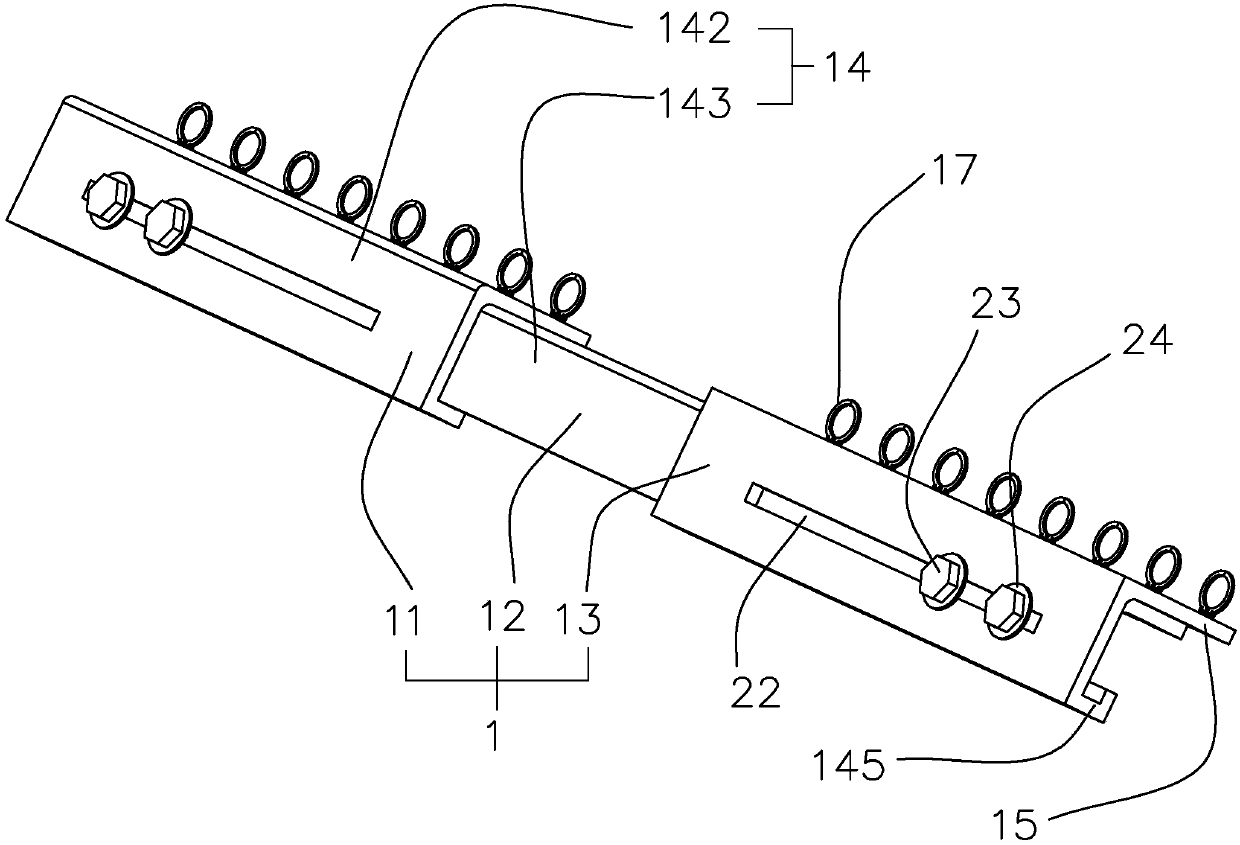
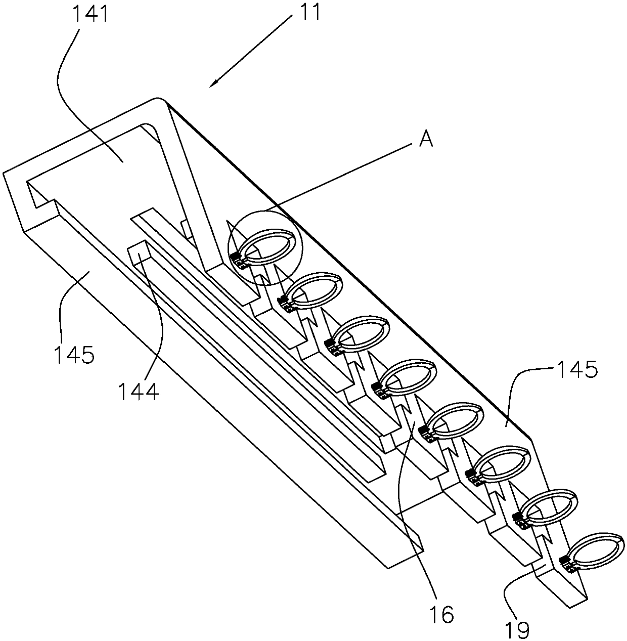
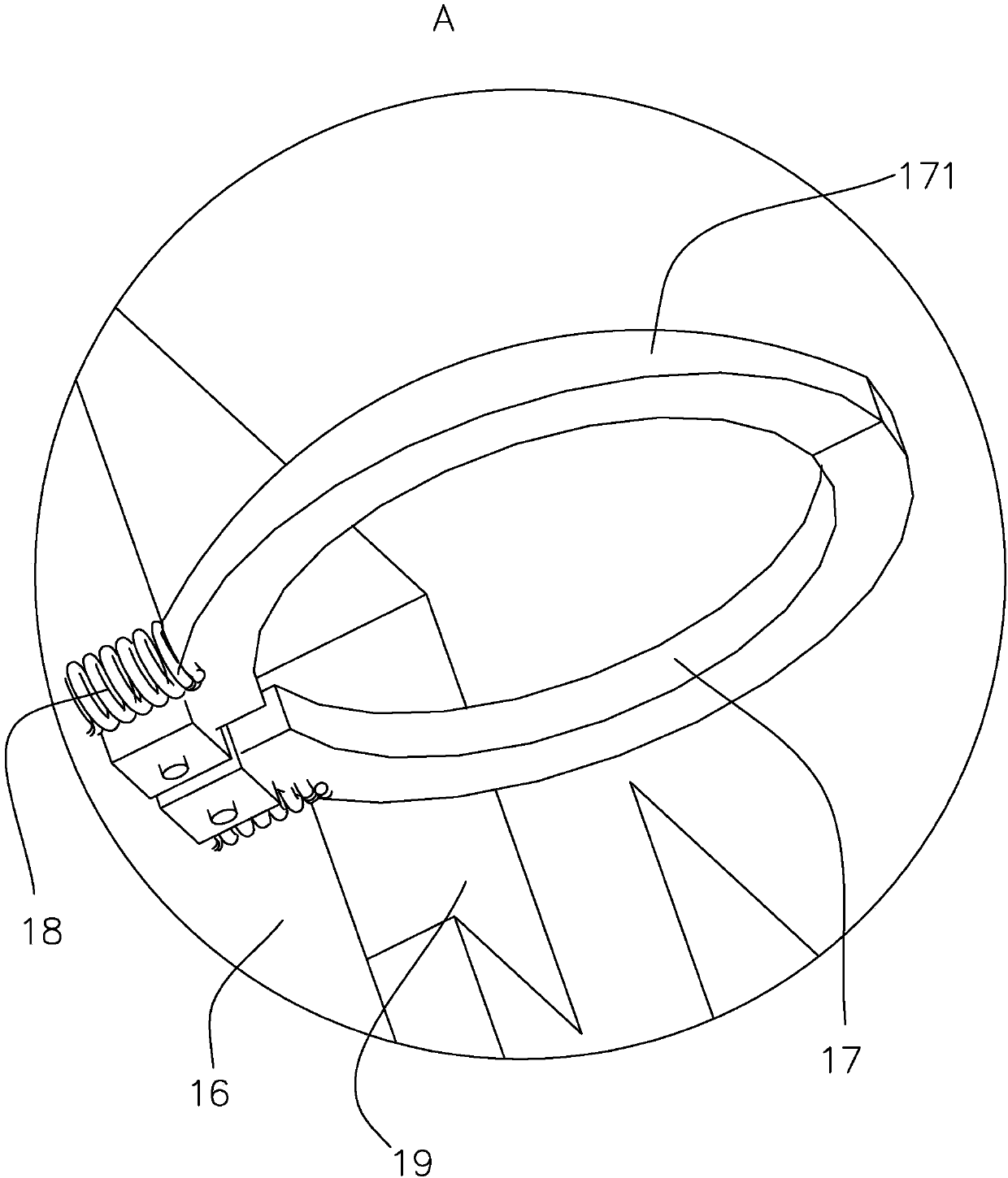
[0033] A cable clamp rail such as figure 1 and figure 2 , including a cable clip 1, a plurality of cable grooves 19 are opened on the cable clip 1, and the cable clip 1 includes a component 11, a component 2 12 and a component 3 13, and the component 11 and the component 3 13 are respectively slidably connected to the component two At both ends of 12, a locking device is provided between component one 11 and component two 12, and a locking device is also arranged between component three 13 and component two 12. The first component 11, the second component 12 and the third component 13 are all set in an "L" shape, and the first component 11, the second component 12 and the third component 13 all include a horizontally arranged connecting plate 14 and a vertically arranged wiring board 15, and the wiring The groove 19 is disposed on the wiring board 15 . The connecting plate 14 includes a fixed plate 142 and a moving plate 141, the fixed plate 142 is set on the second compone...


PUM


Abstract

The present invention relates to a cable clamp rail, pertaining to the technical field of cable equipments. The cable clamp rail comprises a cable arrangement clip. The cable arrangement clip is provided with a plurality of cable arrangement slots. The cable arrangement clip comprises a component one, a component two and a component three. The component one and the component three are separately slidably connected at both ends of the component two, locking device(s) are arranged between the component one and the component two, and the locking device(s) are also arranged between the component three and the component two. When the cable clamp rail is used, the operator can adjust the length of the cable arrangement clip according to the size of the type and slide the component one and the component three at both ends of the component two, so that the length of the cable arrangement clip is changed to meet the using demand of the type. The structure of the cable clamp rail is simple, compact and reasonable. The cable clamp rail can be used for cable guidance on a cabinet frame and reducing the tension of installed cables. The length of an installing rail is adjustable, so that the installing rail can flexibly adapt the given fixing distance between two installing frames, and thus the cable clamp rail has a relative large application range.

Description

technical field [0001] The invention relates to the technical field of cable equipment, in particular to a cable clamp rail. Background technique [0002] Electric shovels are also called rope shovels and cable shovels, that is, mechanical electric excavators are single-bucket excavators that use gears, chains, cable pulleys and other transmission parts to transmit power. Its production has a history of 100 years, and the largest bucket currently produced The capacity has exceeded 50 cubic meters. Small and medium-sized machines are driven by diesel engines or diesel-electric motors, while large machines are driven by electric motors or units, driven by external input electric energy, and are the main mining equipment for various modern open-pit mines. [0003] With the development of society today, a lot of electric shovel equipment uses high-voltage electric energy, and electric shovels need to roll cables to go back and forth, so they are faced with the problem of cable ...

Claims


Application Information

Patent Timeline
Patent Type & Authority Applications(China)
IPC IPC(8): H02G3/02
CPCH02G3/02
Inventor 丁力
Owner WUXI UNITE ENERGY TECH CO LTD
Why Eureka
Try Eureka