Fireproof electrical cabinet

A technology for electrical cabinets and electrical appliances, which is applied to electrical equipment shells/cabinets/drawers, electrical components, fire rescue, etc. It can solve problems such as fires and losses that are easy to cause, and achieve the effects of avoiding electric shock and being easy to use

Inactive Publication Date: 2018-04-06
HENAN LONGYU INFORMATION TECH CO LTD
View PDF2 Cites 4 Cited by
  • Summary
  • Abstract
  • Description
  • Claims
  • Application Information

AI Technical Summary

Problems solved by technology

[0002] At present, there are often a large number of lines and electrical appliances in the electrical cabinets on the market. During the use of electrical components, due to excessive temperature or short circuit, it is easy to cause fire, which will cause great losses, and it is very likely to burn other items. , causing greater losses, and if the bottom of the electrical cabinet touches the ground, it will be unstable. Therefore, it is very necessary to provide a fire-resistant electrical cabinet with fire resistance, slip resistance and ease of use.

Method used


Image

  • Fireproof electrical cabinet
  • Fireproof electrical cabinet

Examples


Embodiment 1

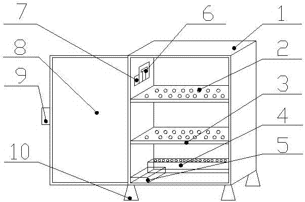
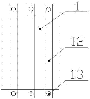
[0015] Such as figure 1 , figure 2 As shown, a fireproof electrical cabinet, which includes a cabinet body 1 and a control box 5, a cabinet door 8 is provided on the front side of the cabinet body 1, and a buckle 9 is provided on the cabinet door 8, and the The side of the cabinet 1 against the wall is provided with a fixed rod 11, the fixed rod 11 is provided with a screw hole 12, the bottom of the cabinet 1 is provided with a tapered foot pad 10, and the inner wall of the cabinet 1 A baffle plate 3 is arranged in the horizontal direction, and a leak hole 2 is arranged on the baffle plate 3, and an electrical main switch 6 and a temperature sensor 7 are arranged on the inner wall of the cabinet body 1, and the electrical main switch 6 and the temperature sensor 7 are all connected with the control box 5, and the control box 5 is connected with the inert gas box 4.

[0016] Beneficial effects of the present invention: the present invention is equipped with a timing device, ...

Embodiment 2

[0018] Such as figure 1 , figure 2 As shown, a fireproof electrical cabinet, which includes a cabinet body 1 and a control box 5, a cabinet door 8 is provided on the front side of the cabinet body 1, and a buckle 9 is provided on the cabinet door 8, and the The side of the cabinet 1 against the wall is provided with a fixed rod 11, the fixed rod 11 is provided with a screw hole 12, the bottom of the cabinet 1 is provided with a tapered foot pad 10, and the inner wall of the cabinet 1 A baffle plate 3 is arranged in the horizontal direction, and a leak hole 2 is arranged on the baffle plate 3, and an electrical main switch 6 and a temperature sensor 7 are arranged on the inner wall of the cabinet body 1, and the electrical main switch 6 and the temperature sensor 7 are all connected with the control box 5, the control box 5 is connected with an inert gas box 4, the described inert gas box 4 is provided with a nozzle hole, the control box 5 is provided with a control switch, a...


PUM


Abstract

The invention relates to a fireproof electrical cabinet. The fireproof electrical cabinet includes a cabinet body and a control case. The cabinet body is provided with a cabinet door on the front sidethereof. The cabinet door is provided with a buckle thereon. The cabinet body is provided with fixing levers on the side surface which leans against the wall. The fixing levers are provided with threaded holes thereon. The bottom part of the cabinet body is provided with conical foot pads. The internal walls of the cabinet body are horizontally provided with baffle plates thereon. Each baffle plate is provided with leakage holes thereon. The internal walls of the cabinet body are provided with an electric appliance master switch and a temperature sensor thereon. The electrical appliance master switch and the temperature sensor are both in connection to the control case. The control case is connected to an inert gas case. According to the invention, the fireproof electrical cabinet has theadvantages of fire resistance, slippery resistance and easy usage.

Description

technical field [0001] The invention belongs to the technical field of electrical cabinets, and in particular relates to a fireproof electrical cabinet. Background technique [0002] At present, there are often a large number of lines and electrical appliances in the electrical cabinets on the market. During the use of electrical components, due to excessive temperature or short circuit, it is easy to cause fire, which will cause great losses, and it is very likely to burn other items. , causing greater losses, and if the bottom of the electrical cabinet touches the ground, it will be unstable. Therefore, it is very necessary to provide a fireproof electrical cabinet with fire resistance, skid resistance and ease of use. Contents of the invention [0003] The purpose of the present invention is to overcome the deficiencies of the prior art and provide a fireproof electric cabinet with fire resistance, skid resistance and ease of use. [0004] The object of the present inv...

Claims


Application Information

Patent Timeline
Patent Type & Authority Applications(China)
IPC IPC(8): H05K5/02H05K5/06A62C3/16A62C37/40
CPCH05K5/0217A62C3/16A62C37/40H05K5/0234H05K5/067
Inventor 王权势
Owner HENAN LONGYU INFORMATION TECH CO LTD
Why Eureka
Try Eureka