
Small tube constrictor for PVC tube

A shrink tube, small-scale technology, applied in applications, household appliances, tubular objects, etc., can solve problems such as construction inconvenience

Active Publication Date: 2018-05-04
苏祥管道科技江苏有限公司
View PDF4 Cites 0 Cited by
  • Summary
  • Abstract
  • Description
  • Claims
  • Application Information

AI Technical Summary

Problems solved by technology

Caused some inconvenience to the construction

Method used


Image

  • Small tube constrictor for PVC tube
  • Small tube constrictor for PVC tube
  • Small tube constrictor for PVC tube

Examples


Embodiment Construction

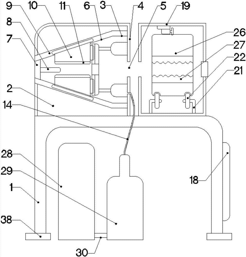
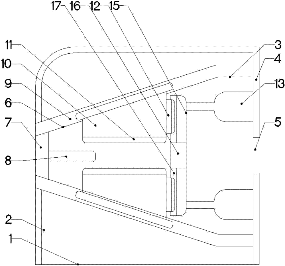
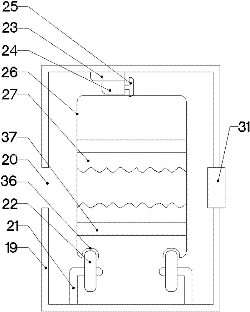
[0020] The present invention is specifically described below in conjunction with accompanying drawing, as Figure 1-4 As shown, it includes a rectangular support frame 1, and a tube shrinking device is arranged above the rectangular support frame 1. The tube shrinking device consists of a cylinder that is located at one end of the upper surface of the rectangular support frame 1 and is fixedly connected with the rectangular support frame 1 in the horizontal direction. Entity 2, a cylindrical through hole 3 located at one end of the center of the cylindrical entity 2 and fixedly connected to the cylindrical entity 2 in the horizontal direction, a stopper 4 located on the inner surface of one end of the cylindrical through hole 3 and fixedly connected to the cylindrical through hole 3, The circular hole 5 fixedly connected with the baffle piece 4 at the center of the baffle piece 4, the conical through hole 6 located at the other end of the center of the cylindrical entity 2 and ...


PUM


Abstract

The invention discloses a small tube constrictor for a PVC tube. The small tube constrictor for the PVC tube comprises a rectangular supporting frame. A tube constriction device is arranged on the upper portion of the rectangular supporting frame and provided with a telescopic device. The telescopic device is provided with a heating device. The heating device is provided with a rotary motor and aheater. A controller is arranged on one end of the rectangular supporting frame. An oil tank is arranged below the rectangular supporting frame. An oil pump is arranged on one side of the oil tank. The controller is electrically connected with the rotary motor, the heater and the oil pump. The small tube constrictor for the PVC tube has the beneficial effects of being simple in structure and highin practicability.

Description

technical field [0001] The invention relates to the field of butt jointing of PVC pipes, in particular to a small shrinking device for PVC pipes. Background technique [0002] In our current life, PVC pipes are common liquid transportation equipment in our family. However, most of the docking methods are to add a docking port to the PVC pipe, so that the diameter of the docking port will be larger than the diameter of the PVC pipe. In some In certain cases, such as PVC pipes need to pass through small holes in the wall. In this case the interface becomes a hindrance. It caused some inconvenience to the construction. Contents of the invention [0003] The purpose of the present invention is in order to solve the problems referred to above, has designed a kind of small shrinkage device for PVC pipe. [0004] To achieve the above object, the technical solution of the present invention is to include a rectangular support frame, a tube shrinking device is arranged above the ...

Claims


Application Information

Patent Timeline
Patent Type & Authority Applications(China)
IPC IPC(8): B29C57/00B29C35/02B29L23/00B29K27/06
CPCB29C35/02B29C57/00B29K2027/06B29L2023/22
Inventor 赵雪丽
Owner 苏祥管道科技江苏有限公司
Learn More