Supercharge Your Innovation With Domain-Expert AI Agents!

On-site calibration system and method for electronic current transformer

A technology of current transformer and on-site calibration, which is applied in the electric power field to achieve the effect of reducing the number of voltage boost/current boost, reducing repeated movement, and reducing the number of repeated wiring

Active Publication Date: 2020-01-24
NORTH CHINA ELECTRICAL POWER RES INST +2
View PDF4 Cites 0 Cited by
  • Summary
  • Abstract
  • Description
  • Claims
  • Application Information

AI Technical Summary

Problems solved by technology

[0003] In the prior art, the electronic current transformer calibration wiring diagram given in the State Grid Enterprise Standard Q / GDW 690-2011 "On-site Calibration Specifications for Electronic Transformers" is as follows figure 1 shown, using figure 1 The transformer calibration scheme shown can only conduct on-site calibration for one electronic current transformer at a time. For each on-site calibration of one electronic current transformer, it is necessary to disconnect and connect the test line once, and also need to disconnect and connect Secondary test line, and at the same time move the test equipment and auxiliary equipment according to the position of the tested product

Method used


Image

  • On-site calibration system and method for electronic current transformer
  • On-site calibration system and method for electronic current transformer
  • On-site calibration system and method for electronic current transformer

Examples


Embodiment Construction

[0030] The following will clearly and completely describe the technical solutions in the embodiments of the present invention with reference to the accompanying drawings in the embodiments of the present invention. Obviously, the described embodiments are only some, not all, embodiments of the present invention. Based on the embodiments of the present invention, all other embodiments obtained by persons of ordinary skill in the art without making creative efforts belong to the protection scope of the present invention.

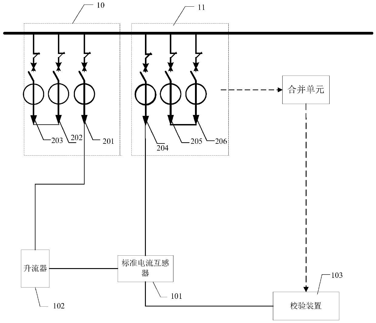
[0031] The embodiment of the present invention provides an electronic current transformer on-site verification system, such as figure 2 As shown, it includes: a standard current transformer 101, a current booster 102, a calibration device 103 and a single bus connection connected to the electronic current transformer under test; wherein,

[0032] In the single bus connection, the three phases of two adjacent intervals 10 and 11 are connected to a tested elect...


PUM


Abstract

The invention provides an electronic current transformer field calibration system and method. The system comprises a standard current transformer, a current increasing device, a calibration device anda single bus connecting wire connected to tested electronic current transformers, wherein according to the single bus connecting wire, three phases which are alternately adjacent to each other are each connected with one tested electronic current transformer, two alternately adjacent two-phase terminals (201) and (204) are connected to the current increasing device and the standard current transformer respectively, in the other two spaced phases, the terminals (202) and (203) are connected, and the terminals (205) and (206) are connected. The problem that the testing process is complex in existing intelligent substation electronic current transformer field calibration is solved, and the field calibration efficiency of the electronic current transformers is improved.

Description

technical field [0001] The invention relates to electric power technology, in particular to an on-site calibration system and method for an electronic current transformer. Background technique [0002] With the continuous development of key technologies in smart grids and smart substations, my country's smart substations are experiencing explosive growth, and the number of smart devices in smart substations is also increasing. For transformers in substations, on-site calibration is required before they are put into operation, and on-site calibration of electronic transformers from smart substations is more complicated than on-site calibration of electromagnetic transformers in traditional substations, and the It takes more time. The on-site verification of the transformer needs to be carried out in a power outage, and cross operations cannot be carried out during this period. Therefore, improving the efficiency of on-site calibration of electronic transformers in smart sub...

Claims


Application Information

Patent Timeline
Patent Type & Authority Patents(China)
IPC IPC(8): G01R35/02
CPCG01R35/02
Inventor 高帅徐占河赵林袁瑞铭丁恒春易忠林周丽霞徐剑锋王慧楠姚敏魏学鹏袁建辉
Owner NORTH CHINA ELECTRICAL POWER RES INST
Features
  • R&D
  • Intellectual Property
  • Life Sciences
  • Materials
  • Tech Scout
  • Unparalleled Data Quality
  • Higher Quality Content
  • 60% Fewer Hallucinations
Learn More