
Improved dust catcher

A dust collector and an improved technology, applied in the board/panel/desk of the substation/switchgear, the layout details of the substation/switch, electrical components, etc. , to achieve the effect of stable power supply, high safety and simple structure

Inactive Publication Date: 2018-05-29
广州快舟智能环保科技有限公司
View PDF4 Cites 0 Cited by
  • Summary
  • Abstract
  • Description
  • Claims
  • Application Information

AI Technical Summary

Problems solved by technology

[0002] Industrial dust collectors are widely used in industrial production. However, industrial dust collectors have relatively high power. In some factories, they are specially equipped with distribution box devices for plugging and power supply of dust collectors. There are electrical connection blocks in the distribution box. However, these The setting mode of the electrical connector is single, and the internal conductive sheet is set relatively outside. This conductive sheet is easily touched by the metal sheet or metal rod. Therefore, when people who lack safety awareness insert the metal rod into the electrical connector Electric shock accidents are easy to occur during the middle, and casualties are caused in severe cases; at the same time, the traditional dust collector is extremely unstable when the power supply is supplied. De-energize the dust collector unexpectedly

Method used


Image

  • Improved dust catcher
  • Improved dust catcher
  • Improved dust catcher

Examples


Embodiment Construction

[0023] All features disclosed in this specification, or all disclosed steps in a method or process, may be combined in any way except mutually exclusive features and / or steps.

[0024] Any feature disclosed in this specification (including any accompanying claims, abstract and drawings), unless expressly stated otherwise, may be replaced by other equivalent or alternative features serving a similar purpose. That is, unless expressly stated otherwise, each feature is but one example of a series of equivalent or similar features.

[0025] Combine below Figure 1-5 The present invention will be described in detail.

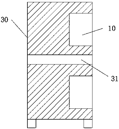
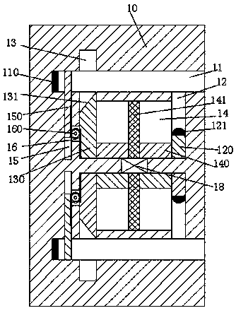
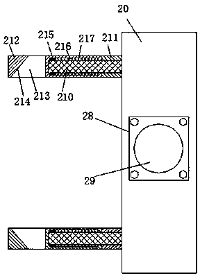
[0026] refer to Figure 1-5 , according to an embodiment of the present invention, an improved precipitator device includes a distribution box 30 and an electrical coupling 20 connected to the precipitator. The above-mentioned electrical sockets 10 are respectively provided with insertion slots 11 with their beginnings facing the right up and down, and the electri...


PUM


Abstract

The invention discloses an improved dust catcher. The dust catcher comprises a power distribution box and an electrical connector, wherein the electrical connector is connected with the dust catcher,at least more than two groups of electrical connection bases are vertically partitioned and arranged in the power distribution box by a partition plate, insertion grooves are vertically and correspondingly formed in the electrical connection bases and are provided with opening ends facing rightwards, first sliding push grooves, second sliding push grooves and third sliding push grooves are also vertically and correspondingly formed in the electrical connection bases and are provided with opening ends facing the insertion grooves, sliding push cavities are formed between the first sliding pushgrooves and the second sliding push grooves and communicate with each other, sliding push plates are movably arranged in the sliding push grooves, sliding push arms are movably arranged in the first sliding push grooves, locking arms are movably arranged in the second sliding push grooves and penetrate through the insertion grooves, and first inclined prop-against surfaces are arranged at end surfaces, facing the insertion grooves, of the locking arms.

Description

technical field [0001] The invention relates to the field of dust collectors, in particular to an improved dust collector device. Background technique [0002] Industrial dust collectors are widely used in industrial production. However, industrial dust collectors have high power. Some factories are specially equipped with distribution box devices for plugging and supplying power to dust collectors. The electrical connection socket has a single setting mode, and the inner conductive sheet is set relatively to the outside. This conductive sheet is easily contacted by the metal sheet or metal rod. Therefore, when a person who lacks safety awareness inserts the metal rod into the electrical socket At the same time, the traditional dust collector is extremely unstable during power supply. If you accidentally kick the electrical connector or trip over the wire, it will cause the electrical connector to fall off. Unexpectedly power off the dust collector. SUMMARY OF THE INVENTI...

Claims


Application Information

Patent Timeline
IPC IPC(8): H02B1/04H02B1/46B03C3/66
CPCH02B1/04B03C3/66H02B1/46
Inventor 王晓炜
Owner 广州快舟智能环保科技有限公司
Learn More