Antenna system and terminal

An antenna system and antenna technology, applied in the field of communication, can solve the problems that communication equipment cannot work in the full frequency band and cannot meet the data transmission rate requirements of 4.5G/5G communication, and achieve the effect of improving data transmission efficiency.

Inactive Publication Date: 2018-06-22
AAC PRECISE MFG TECH CHANGZHOU
View PDF11 Cites 28 Cited by
  • Summary
  • Abstract
  • Description
  • Claims
  • Application Information

AI Technical Summary

Problems solved by technology

[0003] The inventors have found that there are at least the following problems in the prior art: with the advent of the 4.5G / 5G mobile communication era, existing communication equipment will not be able to meet the data transmission rate requirements of 4.5G / 5G communication, and the existing full-screen Communication equipment cannot work in the full frequency band, and the corresponding mobile phone card must use a mobile phone that meets the operating frequency of the mobile phone card. Therefore, in a full-screen mobile phone, it is necessary to provide communication equipment with a full frequency band working range, so as to meet the transmission requirements of the communication equipment for carrier aggregation.

Method used


Image

  • Antenna system and terminal
  • Antenna system and terminal
  • Antenna system and terminal

Examples


Embodiment Construction

[0035] In order to make the purpose, technical solutions and advantages of the embodiments of the present invention more clear, various implementation modes of the present invention will be described in detail below in conjunction with the accompanying drawings. However, those of ordinary skill in the art can understand that in each implementation manner of the present invention, many technical details are proposed in order to enable readers to better understand the present invention. However, even without these technical details and various changes and modifications based on the following implementation modes, the technical solution claimed in the present invention can also be realized.

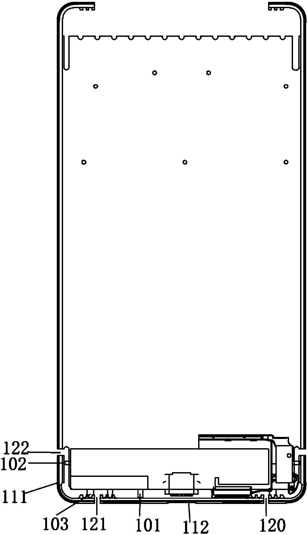
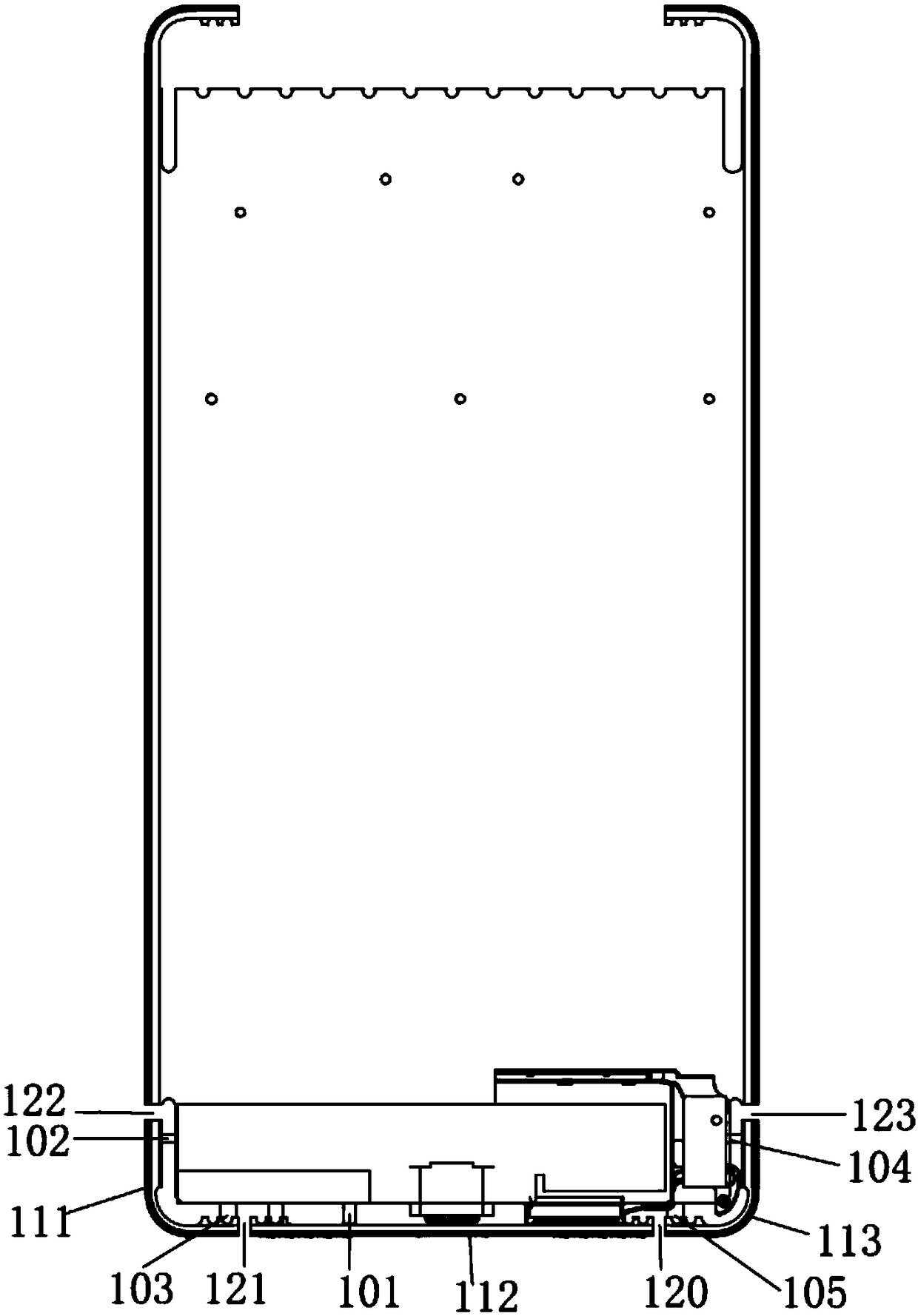
[0036] A first embodiment of the invention relates to an antenna system. The specific structure is as figure 1 As shown, the antenna system includes: a first antenna 111, a second antenna 112, a first feed point 101, a second feed point 102 and a first ground point 103; wherein, the first a...


PUM


Abstract

The embodiment of the invention relates to the field of communication equipment and discloses an antenna system and a terminal. The antenna system comprises a first antenna, a second antenna, a firstfeeding point, a second feeding point and a first grounding point, wherein the first antenna and the second antenna are obtained through cutting a metal border of the terminal from a breaking joint, asecond breaking joint and a third breaking joint; the first antenna is located between the first breaking joint and the second breaking joint and connected with the first feeding point; the second antenna is located between the second breaking joint and the third breaking joint and connected with the second feeding point; the first grounding point is located at the edge position, close to the second breaking joint, of the first antenna; the first breaking joint and the second breaking joint are located on a short-edge side surface of the metal border of the terminal; the third breaking jointis located on a first long-edge side surface of the metal border of the terminal; and the first feeding point and the second feeding point are arranged on a printed circuit board. According to the antenna system, the terminal can work on a full band, the condition that a high frequency and a low frequency can simultaneously exist in different states is met and the requirements of carrier aggregation are met.

Description

technical field [0001] Embodiments of the present invention relate to the technical field of communications, and in particular to an antenna system and a terminal. Background technique [0002] With the continuous development of handheld communication products, the appearance size and aesthetic design of mobile phones are the focus of attention. The screen-to-body ratio of mobile phones is one of the aesthetic factors. Even more tense, and the most important thing for communication products is the communication quality. The current communication equipment has higher and higher requirements for communication quality. [0003] The inventors have found that there are at least the following problems in the prior art: with the advent of the 4.5G / 5G mobile communication era, existing communication equipment will not be able to meet the data transmission rate requirements of 4.5G / 5G communication, and the existing full-screen Communication equipment cannot work in the full frequen...

Claims


Application Information

Patent Timeline
Patent Type & Authority Applications(China)
IPC IPC(8): H01Q1/36H01Q1/44H01Q1/48H01Q1/50H01Q1/24H01Q5/335
CPCH01Q1/244H01Q1/36H01Q1/44H01Q1/48H01Q1/50H01Q5/335
Inventor 邱孝钧王朋朱博
Owner AAC PRECISE MFG TECH CHANGZHOU
Why Eureka
Try Eureka