Motor and traction motor junction box thereof

A traction motor and junction box technology, applied in the field of rail transit, can solve the problems of limiting the size of the traction motor junction box 1 and limited space, and achieve the effect of large creepage distance and large electrical clearance

Pending Publication Date: 2018-10-23
CSR ZHUZHOU ELECTRIC CO LTD
View PDF8 Cites 1 Cited by
  • Summary
  • Abstract
  • Description
  • Claims
  • Application Information

AI Technical Summary

Problems solved by technology

Since the traction motor junction box 1 is located in the middle of the bogie and the motor frame 2, and the space in this area is limited, the size of the traction motor junction box 1 is limited

Method used


Image

  • Motor and traction motor junction box thereof
  • Motor and traction motor junction box thereof
  • Motor and traction motor junction box thereof

Examples


Embodiment Construction

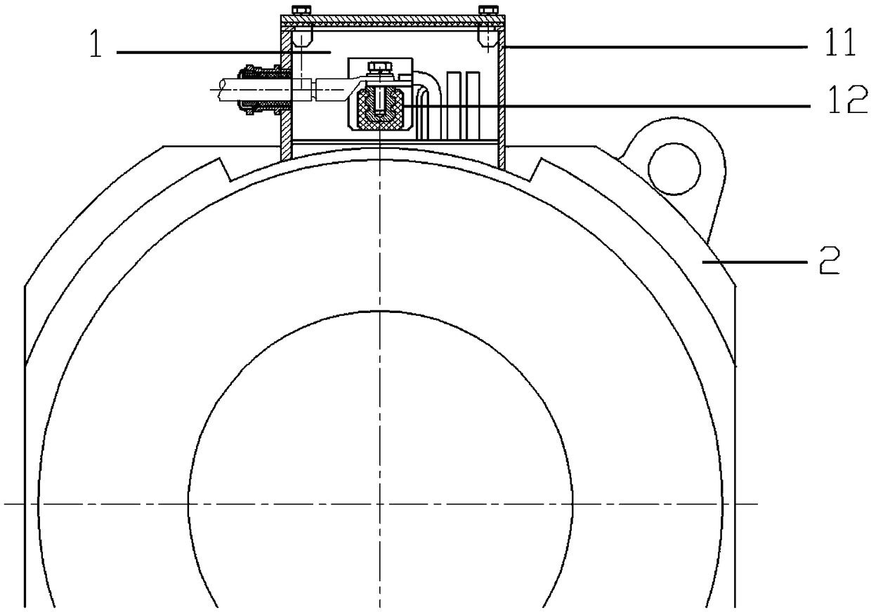
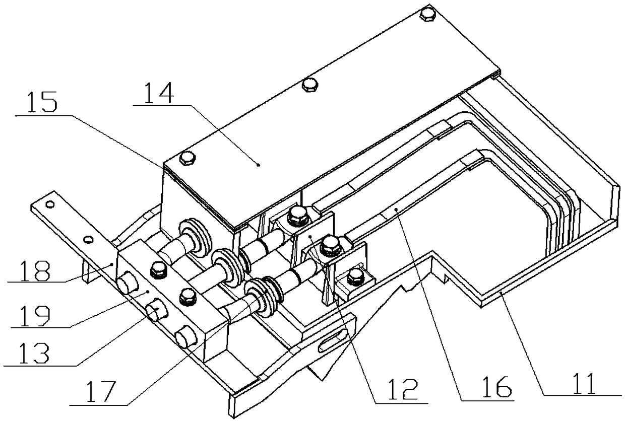
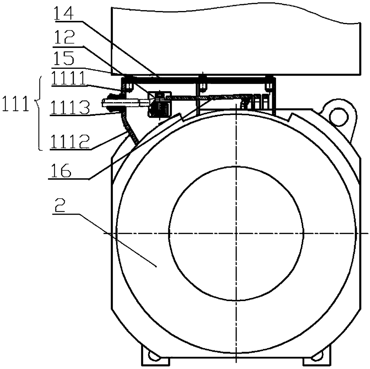
[0020] The core of the present invention is to provide a traction motor junction box 1, which can meet the electrical clearance and creepage distance of the traction motor junction box 1 under different network voltages, and is also conducive to the outlet of the three-phase cable 13; another aspect of the present invention The core is to provide a motor including the above traction motor junction box 1, which is suitable for working under different network voltages and is convenient for wiring.

[0021] In order to enable those skilled in the art to better understand the technical solution of the present invention, the present invention will be further described in detail below in conjunction with the accompanying drawings and specific embodiments.

[0022] Please refer to figure 2 , figure 2 It is a structural diagram of a specific embodiment of the traction motor junction box 1 provided by the present invention.

[0023] In the specific embodiment of the first traction ...


PUM


Abstract

The invention discloses a traction motor junction box (1), which comprises a junction box main body (11). The junction box main body (11) is fixed on a motor base (2); the junction box main body (11)is internally provided with a three-phase cable line (13) and a wiring seat (12) arranged oppositely to a deflection wheel; the wiring seat (12) is used for fixing the three-phase cable line (13); andthe wiring seat (12) is far away from the vertical symmetrical surface of the motor and arranged oppositely to the deflection wheel. The self arc of the motor side wall is effectively used to compensate the height difference between the actual height of the wiring seat and the allowed height, and a large creepage distance and a large electrical gap are achieved. According to the above traction motor junction box (1), in a condition of not changing the motor main body structure, the problem of limited space below a bogie can be effectively solved, and outgoing of the three-phase cable line (13) is also facilitated.

Description

technical field [0001] The invention relates to the field of rail transportation, in particular to a motor. The invention also relates to a traction motor junction box. Background technique [0002] The motor is one of the important parts of the electric locomotive, which is installed on the bogie under the car body. When the electric locomotive is in the traction state, the motor converts electrical energy into mechanical energy, which makes the wheel set rotate and then drives the locomotive to run. [0003] Please refer to figure 1 , figure 1 It is a schematic diagram of a connection structure between a typical traction motor junction box 1 and a motor frame 2 in the prior art. The traction motor junction box 1 is generally installed directly above the traction motor frame 2 and below the bogie (not shown in the figure). The traction motor terminal box 1 includes a terminal box main body 11 and a terminal base 12 disposed inside the terminal box main body 11 , and th...

Claims


Application Information

Patent Timeline
Patent Type & Authority Applications(China)
IPC IPC(8): H02K5/22
CPCH02K5/225H02K5/22
Inventor 赵延召刘勇于海涛随帅民崔斯柳
Owner CSR ZHUZHOU ELECTRIC CO LTD
Why Eureka
Try Eureka