Seepage drainage device with replaceable filter core in tailings pond and filter core replacement method

A replacement method and filter element technology, which is applied in soil drainage, construction, agriculture, etc., can solve the problems of long length of seepage pipe, difficulty in replacing the filter element of the seepage pipe in situ, and inability to lay filter material, etc., so as to achieve the goal of compression Effect

Active Publication Date: 2019-09-10
HOHAI UNIV
View PDF12 Cites 0 Cited by
  • Summary
  • Abstract
  • Description
  • Claims
  • Application Information

AI Technical Summary

Problems solved by technology

[0004] The Chinese invention patent with the patent number CN20091006362.6 discloses a chemical clogging and seepage prevention device for tailings dams, but there is still no good solution to the comprehensive clogging problem of tailings drainage facilities
The Chinese Utility Model Patent No. CN99256709.2 discloses a detachable drainage and pressure relief well, which uses filter cloth and backfill sand adjacent to the well pipe to perform filtering functions, and is used for embankment foundation treatment of embankment construction projects along rivers and rivers. , since most of the tailings that need to be drained are in the form of slurry, and when the drainage pipe is laid after the construction of the tailings pond is completed, the filter material cannot be laid around the drainage pipe, so the filter body of the removable drainage decompression well The replacement method does not apply to horizontal seepage pipes placed horizontally in tailings ponds
However, the seepage pipe used in the tailings pond is long and placed horizontally, which makes it very difficult to replace the filter element of the seepage pipe in situ, and there is no suitable solution

Method used


Image

  • Seepage drainage device with replaceable filter core in tailings pond and filter core replacement method
  • Seepage drainage device with replaceable filter core in tailings pond and filter core replacement method
  • Seepage drainage device with replaceable filter core in tailings pond and filter core replacement method

Examples


Embodiment Construction

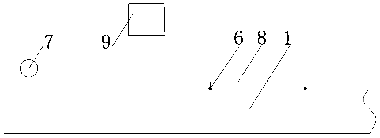
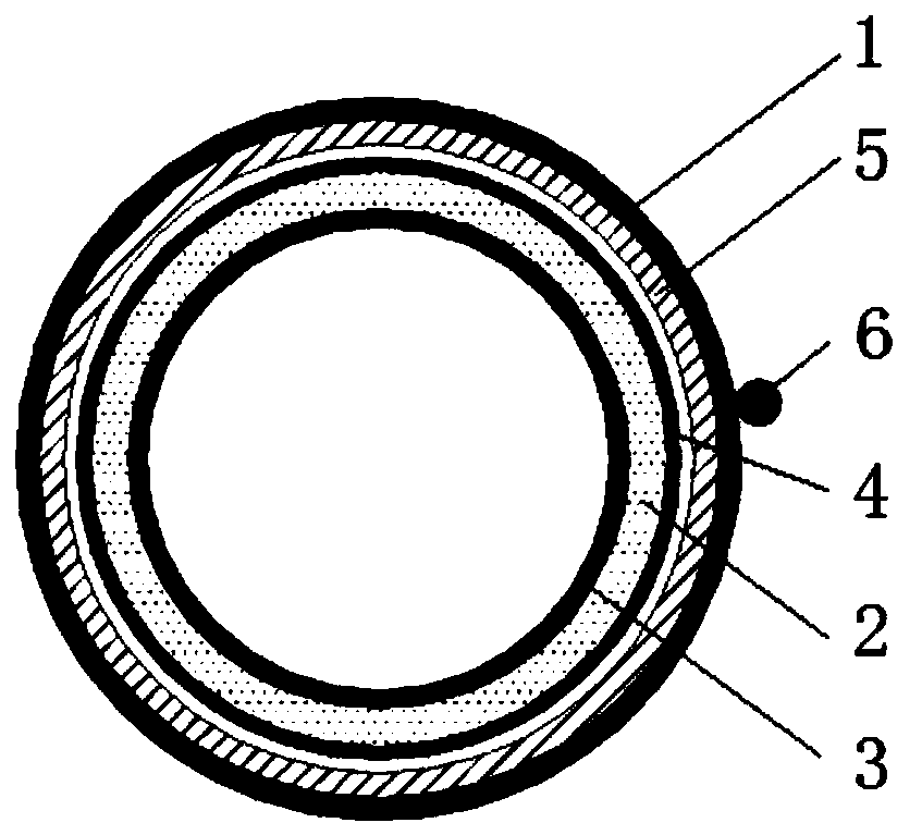
[0024] Such as figure 1 , figure 2 As shown, the seepage drainage device includes a seepage drainage pipe and a clogging monitoring system connected to the seepage drainage pipe, wherein the seepage drainage pipe includes an outer floral tube 1, a filter element 2 and an inner floral tube 3, and the clogging monitoring system includes a seepage pressure meter 6, flow meter 7 and processor 9.

[0025] The outer flower tube 1 is buried in the pre-drilled hole and will not be pulled out, and is in direct contact with the tailings, so as to support the external tailings and form the inner space; the outer flower tube 1 is made of anti-corrosion UPVC Material, the flower tube diameter is 56-90mm, the opening diameter is 12-15mm, the opening rate is 13%-15%, and the water guide section at the end of the flower tube does not need to be drilled. The outer flower tube is made in sections, and the sections are connected by pipe hoops.

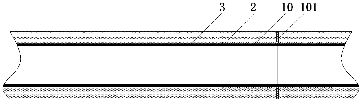
[0026] Such as image 3 As shown, the filter ...


PUM


Abstract

The invention discloses a seepage draining device capable of replacing a filter element in a tailing pond and a filter element replacing method. The seepage draining device comprises a seepage draining pipe and a clogging monitoring system connected with the seepage draining pipe; the seepage draining pipe comprises an outer-layer perforated pipe, a filter element closely attached to the inner wall of the outer-layer perforated pipe and an inner-layer perforated pipe arranged in the filter element in a sleeved mode; and an elastic sponge body closely attached to the outer-layer perforated pipeis selected as the filter element. When the filter element is replaced, it is guaranteed that tailing sand does not flood into the pipe after the filter element is extracted out through a first temporary casing pipe for isolating the tailing sand; and the filter element is compressed through a second temporary casing pipe, and therefore in-situ replacement of the filter element of the horizontalseepage draining pipe is achieved. Compared with the prior art, after the seepage draining pipe is clogged, the seepage draining pipe can continue to be used after the filter element is replaced in situ, re-drilling and seepage draining pipe laying are not needed, and the engineering cost is reduced.

Description

technical field [0001] The invention relates to a seepage discharge device for a tailings pond, in particular to a seepage discharge device and a filter replacement method for a replaceable filter core in a tailings pond. Background technique [0002] Tailings pond is one of the three major production facilities of metals, non-metals and mines. It is composed of dams to intercept valley mouths or enclosures. It is used to stockpile metal or non-metal mines for ore selection, and discharge tailings or other industrial waste. place. The tailings pond is a source of man-made debris flow hazard with high potential energy, and there is a danger of dam failure. Once it fails, it is likely to cause serious accidents, which is a major source of hazard. At present, more than 90% of the tailings ponds are built by the upstream method, and the tailings are formed and transported into the reservoir dams in the form of water-sand mixture. There is a seepage line that will raise the dam...

Claims


Application Information

Patent Timeline
Patent Type & Authority Patents(China)
IPC IPC(8): E02B11/00
Inventor 王媛刘胜冯迪田彦柴思嘉
Owner HOHAI UNIV
Why Eureka
Try Eureka