Antenna electric downtilt control device

A control device and antenna electrical technology, applied to antennas, electrical components, etc., can solve problems such as adjustment errors and complex structures

Active Publication Date: 2018-07-24
COMBA TELECOM TECH (GUANGZHOU) CO LTD
View PDF4 Cites 2 Cited by
  • Summary
  • Abstract
  • Description
  • Claims
  • Application Information

AI Technical Summary

Problems solved by technology

The structure of the traditional electronic downtilt transmission device is relatively com

Method used


Image

  • Antenna electric downtilt control device
  • Antenna electric downtilt control device
  • Antenna electric downtilt control device

Examples


Embodiment Construction

[0028]In order to make the object, technical solution and advantages of the present invention clearer, the present invention will be further described in detail below in conjunction with the accompanying drawings and specific implementation methods. It should be understood that the specific embodiments described here are only used to explain the present invention, and do not limit the protection scope of the present invention.

[0029] It should be noted that when an element is referred to as being “fixed on”, “installed on”, “disposed on” or “installed on” another element, it may be directly on the other element or there may be an intervening element. When an element is considered to be "connected" to another element, it may be directly connected to the other element or there may be an intervening element at the same time; further, when an element is considered to be "fixed drive connected" to another element, both may It can be fixed in a detachable connection mode, and can ...


PUM


Abstract

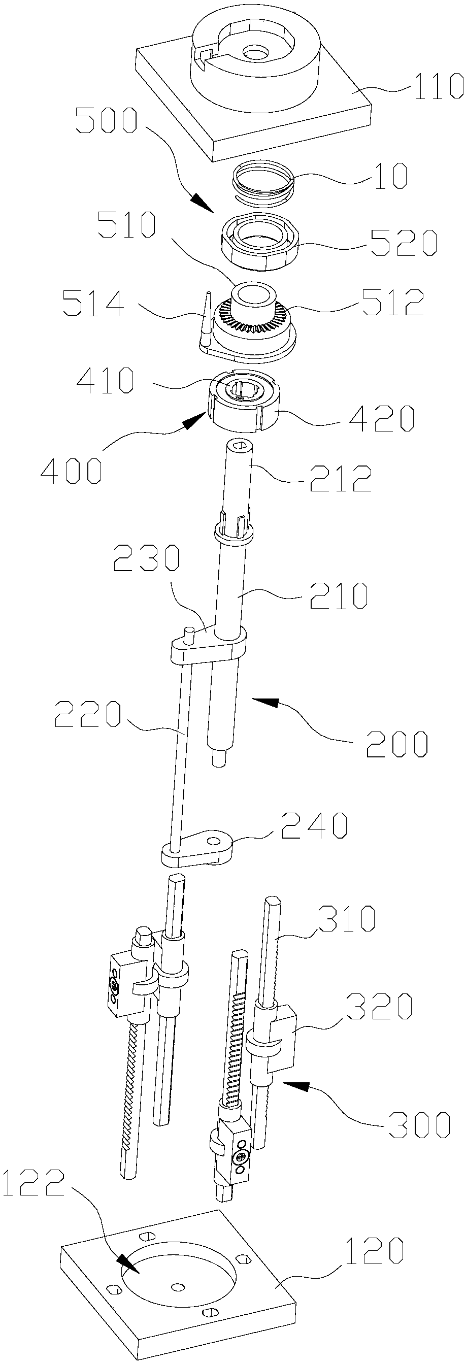
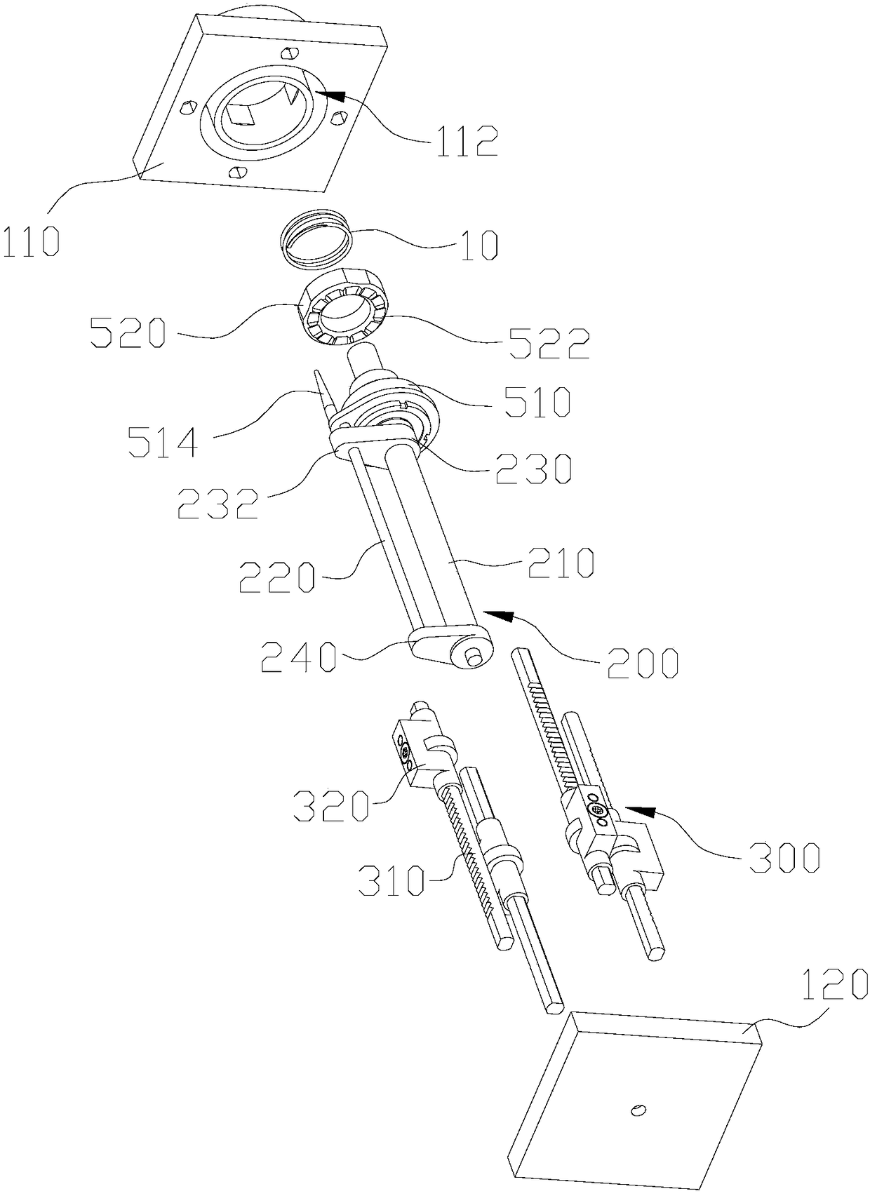
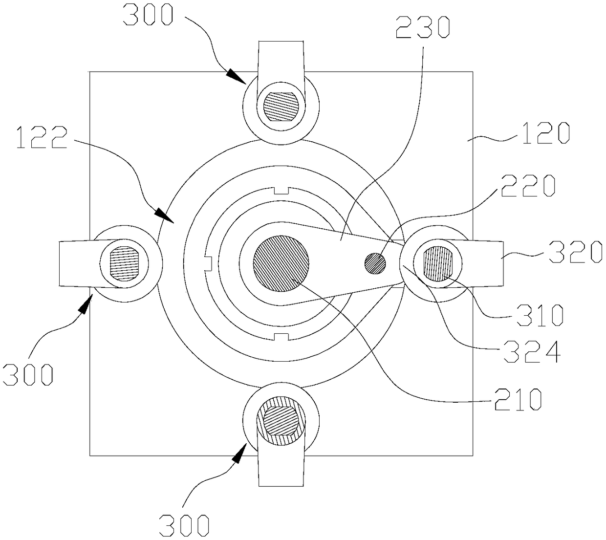
The invention discloses an antenna electric downtilt control device comprising an input component. The input component comprises a reciprocating screw, a limiting rod and a moving baffle block. The reciprocating screw can rotate along a first rotating direction and drive the moving baffle block to reciprocate along an axis direction of the reciprocating screw, the reciprocating screw can rotate along an opposite direction of the first rotation direction and drives the moving baffle block and the limiting rod to revolve along an axis of the reciprocating screw, and the moving baffle block is provided with a pressing end. The antenna electric downtilt control device also comprises an output component which comprises a stroke rod fixed to a first preset position and a mounting member slidablyengaged with the stroke rod, and the pressing end of the moving baffle block is in selective pressing engagement with the corresponding mounting member. According to the antenna electric downtilt control device, the independent and precise control of the downtilt angles of two or more beam antennas can be achieved, and the device has the advantages of a compact structure and a small adjustment error.

Description


Claims


Application Information

Patent Timeline
Owner COMBA TELECOM TECH (GUANGZHOU) CO LTD
Why Eureka
Try Eureka