coil device

A coil device and coil technology, applied in the direction of transformer/inductor coil/winding/connection, inductor, transformer/inductor parts, etc., can solve the difficulty of miniaturization, the increase of the outer diameter of the secondary side frame, and the leakage characteristics Difficult to stabilize and other issues

Active Publication Date: 2020-10-13
TDK CORPARATION
View PDF6 Cites 0 Cited by
  • Summary
  • Abstract
  • Description
  • Claims
  • Application Information

AI Technical Summary

Problems solved by technology

Therefore, it is difficult to set the interval in the winding axis direction between the primary coil and the secondary coil to a constant thickness, and it is difficult to stabilize the leakage characteristics.
[0005] In addition, in this coil device, in order to form an arc-shaped side wall portion on the secondary side frame, a storage portion is provided inside the side wall portion, and the primary side frame is accommodated in the storage portion, and the secondary side frame The outer diameter becomes larger, and there are still problems such as difficulty in miniaturization

Method used


Image

  • coil device
  • coil device
  • coil device

Examples


Embodiment Construction

[0119] Hereinafter, the present invention will be described based on the embodiments shown in the drawings.

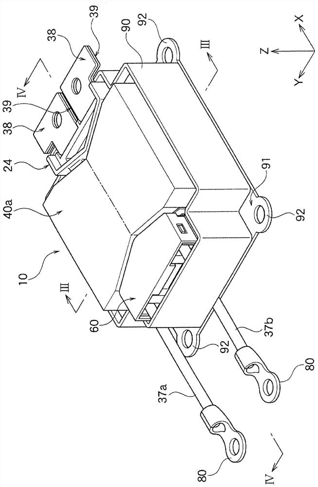
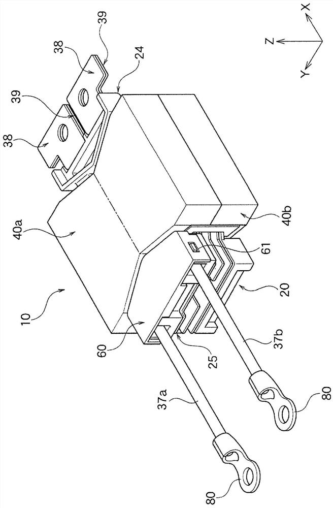
[0120] as Figure 1A The shown transformer 10 of the coil device according to this embodiment is used to step down a high voltage supplied from a high-voltage battery of an electric vehicle or a hybrid vehicle to a low voltage, and to supply the low voltage to a DC / DC of other electrical equipment. converter etc.

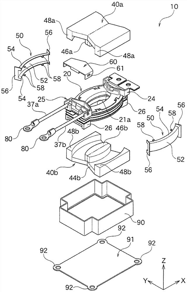
[0121] Such as figure 2 As shown, the transformer 10 has a frame 20 , magnetic cores 40 a and 40 b , a cover 50 , a lead-out winding cover 60 , terminals 80 , a case 90 for accommodating them, and a bottom plate 91 . In addition, in the drawings, the X-axis, Y-axis, and Z-axis are perpendicular to each other, and the Z-axis corresponds to the height (thickness) of the transformer 10 . In the present embodiment, the lower side of the transformer 10 in the Z-axis direction serves as a transformer installation surface. In addition, the Y axis coincides with...


PUM

PropertyMeasurementUnit
hardnessaaaaaaaaaa

Abstract

The coil device can be miniaturized and has stable leakage characteristics. The coil device comprises a framework (20); a first coil part (31) which is composed of a plate-shaped electric conductor; asecond coil part (32) which is composed of a plate-shaped electric conductor and positioned on a different position from the first coil part (31), and a middle coil part (33) positioned between the first coil part (31) and the second coil part (32). A framework (20) comprises a middle framework (23), a first framework (21) and a second framework (22). The middle coil part (33) is wound around a middle cylinder part (236) through a means of tightly attaching with a first intermediate flange portion (231) and a second intermediate flange portion (232), and in a means that the second intermediate flange portion (232) abuts against the opposite side surface of the second coil part (32) of a second end flange part (232), a second cylinder part (226) is combined to the second end of the middlecylinder part (236).

Description

technical field [0001] The present invention relates to a coil device that can be suitably used as a transformer such as a leakage transformer. Background technique [0002] Coil devices are used in various electrical products for various purposes. For example, in a DC / DC converter that steps down a high voltage supplied from a high-voltage battery of an electric vehicle or a hybrid vehicle to a low voltage and supplies the low voltage to other electrical equipment, a coil device is used, generally as a leakage transformer Wait for the transformer to use. [0003] As an example of a coil device, the coil device shown in the following patent document 1 is mentioned, for example. The coil device disclosed in Patent Document 1 has a primary coil and a pair of secondary coils (bus bars) sandwiching the primary coil up and down. In this coil device, a secondary side bobbin insert-molded with a secondary coil is sandwiched between a primary side bobbin around which a primary co...

Claims


Application Information

Patent Timeline
Patent Type & Authority Patents(China)
IPC IPC(8): H01F38/08H01F27/28H01F27/30H01F27/24
CPCH01F27/24H01F27/2847H01F27/306H01F38/08
Inventor 熊谷胜岩仓正明
Owner TDK CORPARATION
Why Eureka
Try Eureka