Coil device

A coil device, coil technology, applied in transformer/inductor coil/winding/connection, preventing/reducing unwanted electrical/magnetic influence, electrical components, etc., can solve problems such as unstable leakage characteristics

Active Publication Date: 2018-06-29
TDK CORPARATION
View PDF9 Cites 8 Cited by
  • Summary
  • Abstract
  • Description
  • Claims
  • Application Information

AI Technical Summary

Problems solved by technology

However, it has been found that the leakage characteristic is not stable in such a general lead-out structure.

Method used


Image

  • Coil device
  • Coil device
  • Coil device

Examples


Embodiment Construction

[0107] Hereinafter, the present invention will be described based on the embodiments shown in the drawings.

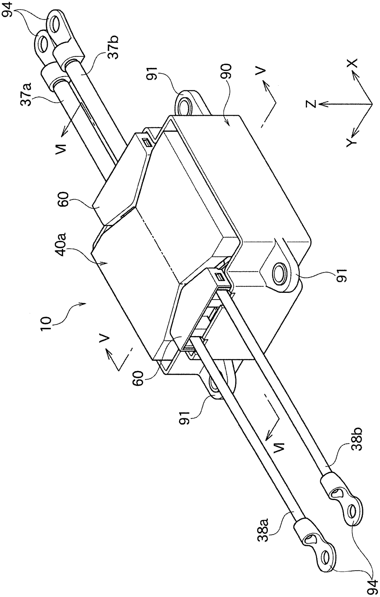
[0108] as figure 1 The shown transformer 10 of the coil device according to the present embodiment is used for, for example, an EV (Electric Vehicle: electric transmission equipment), a PHV (Plug-in Hybrid Vehicle: plug-in hybrid electric vehicle), or a vehicle for commuting (vehicles). A charger or the like is used to constitute a part of an LLC circuit, for example.

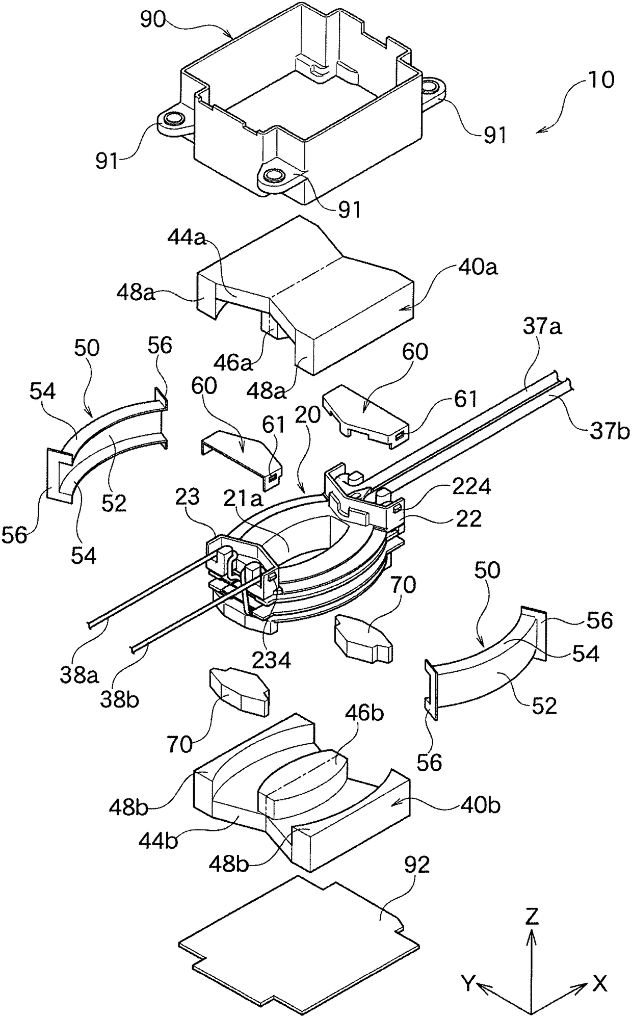
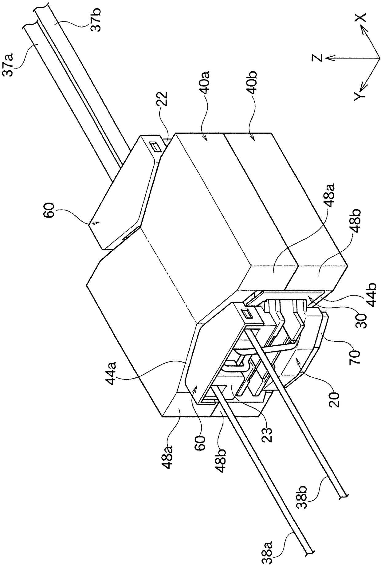
[0109] Such as figure 2 As shown, the transformer 10 has a frame 20 , magnetic cores 40 a and 40 b , a cover 50 , a lead winding cover 60 , a base 70 , a housing 90 for accommodating them, and a bottom plate 92 . In addition, in the drawings, the X-axis, Y-axis and Z-axis are perpendicular to each other, and the Z-axis corresponds to the height (thickness) of the transformer 10 . In the present embodiment, the lower side of the transformer 10 in the Z-axis direction serves as a transformer installat...


PUM


Abstract

The present invention provides a coil device having stable leakage characteristics. The transformer (10) has a bobbin (20) and a coil (300) mounted to the outer circumference of the bobbin (20). At least one pair of first lead portions (37a, 37b) drawn from the coil (300) comprise a rising portion (371a, 371b) extending along the winding axis direction of the coil (300), and a pair of lead-out body portions (373a, 373b) keeping a narrower distance (W1) than the distance between the pair of rising portions (371a, 371b) and extending away from the coil (300); rising portions (371a, 371b) and lead main body portions (373a, 373b) are connected by direction changing portions (372a, 372b), and the direction in which the rising portions (371a, 371b) face is changed in the direction in which the main body portions (373a, 373b) are oriented.

Description

technical field [0001] The present invention relates to a coil device that can be suitably used as a transformer such as a leakage transformer. Background technique [0002] Coil devices are used in various electrical products for various purposes. For example, coil devices can be used in EV (Electric Vehicle: electric transmission equipment), PHV (Plug-in Hybrid Vehicle: plug-in hybrid electric vehicle) or commuter (vehicle) in-vehicle chargers or LLC circuits, etc., and Usually used as transformers such as leakage transformers. [0003] As a coil device, for example, a coil device disclosed in Patent Document 1 described below is known. In the coil device disclosed in Patent Document 1, the adjustment of leakage characteristics is easy, and it is possible to cope with high frequency while achieving a large current. [0004] In the conventional coil device shown in Patent Document 1 and the like, a pair of lead wire portions corresponding to both ends of the winding wire...

Claims


Application Information

Patent Timeline
IPC IPC(8): H01F27/29H01F27/30H01F27/34
CPCH01F27/29H01F27/306H01F27/34
Inventor 熊谷胜岩仓正明比嘉晋士
Owner TDK CORPARATION
Why Eureka
Try Eureka