Coupling convenient to disassemble and assembling method

A technology of couplings and coupling sleeves, which is applied in the direction of couplings, elastic couplings, mechanical equipment, etc., can solve the problems of troublesome disassembly of couplings and lower work efficiency, and achieve convenient and quick disassembly, simple and reasonable structure Effect

Pending Publication Date: 2018-08-24
盐城派威机械有限公司
View PDF0 Cites 4 Cited by
  • Summary
  • Abstract
  • Description
  • Claims
  • Application Information

AI Technical Summary

Problems solved by technology

[0003] However, the existing couplings generally have the problem of troublesome disassembly, and when disassembling, the couplings must be separated by a certain distance along the axial direction of the shaft to ensure the disengagement of the coupling, resulting in a change in the position of at least one shaft , it will be reset and calibrated again when it is installed and used next time, which will obviously reduce work efficiency

Method used


Image

  • Coupling convenient to disassemble and assembling method
  • Coupling convenient to disassemble and assembling method
  • Coupling convenient to disassemble and assembling method

Examples


specific Embodiment approach 1

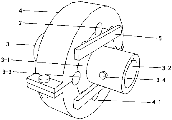
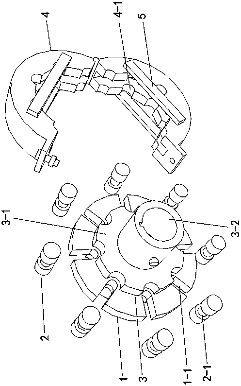
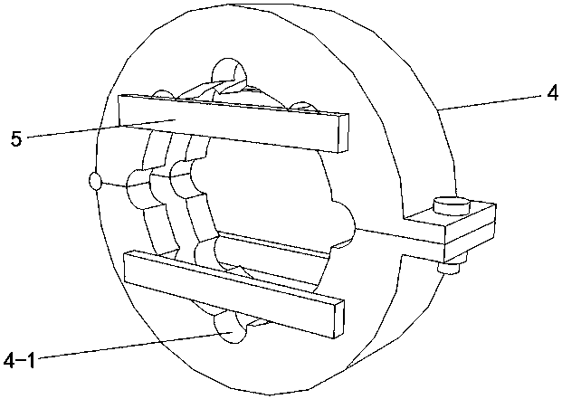
[0017] Specific implementation mode one: as Figure 1~Figure 4 As shown, the present invention discloses a coupling that is easy to disassemble, including two coupling sleeves 3, and the coupling that is easy to disassemble also includes a central positioning plate 1, a positioning hoop 4, and four limit rods 5 and a plurality of positioning cylinders 2, the central positioning plate 1 is a circular plate, the circumferential position of the central positioning plate 1 is provided with a plurality of gaps 1-1 at equal angles along its circumferential direction, and the multiple gaps 1-1 They are arranged radially along the central positioning plate 1, and the plurality of positioning cylinders 2 are set in one-to-one correspondence with the plurality of gaps 1-1, and the middle of the side walls of the plurality of positioning cylinders 2 are all concavely provided with annular locking grooves 2-1, and They are respectively inserted into the corresponding gaps 1-1 through the ...

specific Embodiment approach 2

[0018] Specific implementation mode two: as figure 1 , 4 As shown, this embodiment is a further description of specific embodiment 1. Each side wall of the shaft sleeve 3-2 is provided with a threaded through hole along its radial direction, and the threaded through hole is screwed with a Top wire 3-4. The effect is to fasten the shaft rod to prevent it from breaking away from the shaft sleeve 3-2.

specific Embodiment approach 3

[0019] Specific implementation mode three: as figure 2 As shown, this embodiment is a further description of Embodiment 1 or Embodiment 2, and the number of the plurality of positioning cylinders 2 is 3-8.


PUM


Abstract

The invention provides a coupling convenient to disassemble and a disassembling method, and relates to a coupling and a disassembling method. A plurality of notches are formed in the circumference ofa central positioning plate. Annular clamping grooves are concavely formed in the middle portions of the side walls of positioning cylinders and inserted into the corresponding notches. A plurality offirst arc-shaped clamping grooves are formed in the circumference of each shaft sleeve positioning plate. Shaft sleeve cylinders are coaxially and fixedly connected with the shaft sleeve positioningplates. The two shaft sleeve positioning plates coaxially abut against the two sides of the central positioning plate separately and are clamped between one corresponding ends of the side walls of themultiple positioning cylinders through the multiple first arc-shaped clamping grooves. A positioning clamp is arranged on the circumference of the central positioning plate in a clamping and sleevingmode and provided with a plurality of second arc-shaped clamping grooves. Each second arc-shaped clamping groove is in butt joint with the corresponding first arc-shaped clamping groove to form a positioning round hole matched with the end of the side wall of the corresponding positioning cylinder. Two limiting rods are fixed to each of the two sides of the positioning clamp, so that the shaft sleeve positioning plates are limited in the positioning clamp. The coupling is convenient and fast to disassemble, and the positions of shaft levers do not need to be changed.

Description

technical field [0001] The invention relates to a shaft coupling and a dismounting method, in particular to a shaft coupling that is easy to disassemble and a dismounting method. Background technique [0002] Couplings, also known as couplings, are mechanical components used to firmly connect two shafts in different mechanisms to rotate together and transmit motion and torque. [0003] However, the existing couplings generally have the problem of troublesome disassembly, and when disassembling, the couplings must be separated by a certain distance along the axial direction of the shaft to ensure the disengagement of the coupling, resulting in a change in the position of at least one shaft , the reset calibration will be performed again when it is installed and used next time, which will obviously reduce the work efficiency. [0004] Therefore, designing a coupling that is convenient and quick to disassemble without changing the position of the shaft has always been a resear...

Claims


Application Information

Patent Timeline
Patent Type & Authority Applications(China)
IPC IPC(8): F16D3/48
CPCF16D3/48
Inventor 束长青
Owner 盐城派威机械有限公司
Why Eureka
Try Eureka