Eureka AIR delivers breakthrough ideas for toughest innovation challenges, trusted by R&D personnel around the world.

Transmission ring

A coil and receiving coil technology, applied in the field of electronics, can solve the problems of unrealized, waste of raw materials, etc.

Inactive Publication Date: 2018-08-24
杨培应
View PDF0 Cites 0 Cited by
  • Summary
  • Abstract
  • Description
  • Claims
  • Application Information

AI Technical Summary

Problems solved by technology

[0002] Most of the energy reception and transmission in the prior art adopts wired reception and transmission, but this method only uses electric energy to receive and use it by cable, and has not realized the saving of energy, raw materials and electric energy.
It can be seen that in the process of current energy reception and transmission, excess raw materials are wasted, and energy is lost due to material changes during transmission. Therefore, a backup ring is needed to solve the above-mentioned technical problems existing in the prior art

Method used


Image

  • Transmission ring

Examples


Embodiment Construction

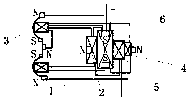
[0015] Such as figure 1 As shown, the backup ring provided by the present invention includes an electric energy output unit, a vacuum coil and an output unit. The backup ring and its various parts of the present invention will be described in detail below.

[0016] Such as figure 1 As shown, the power output unit includes an output frame 1 and a power input coil 5 and a vacuum coil 6 arranged on the output frame 1, the power input coil 5 and the wireless output coil 3 are arranged side by side, and the iron core of the power input coil 5 and the wireless output coil The iron core of 3 is a permanent magnet and the material of vacuum coil 6 and return coil 3 is a hollow iron body of permanent magnet. The electric energy is converted into induced current by flowing through the return coil 2 and vacuum coil 6 and transmitted to the wireless output coil 3 .

[0017] As the first preferred embodiment of the power receiving unit, such as figure 1 As shown, the output frame 1 is a...


PUM


Abstract

The invention relates to a transmission ring. The transmission ring comprises an electric energy output unit; the electric energy output unit comprises an output framework, and an energy receiving coil and a vacuum coil arranged on the output framework; the energy receiving coil and the vacuum coil are arranged in parallel; the iron core of the energy receiving coil and the iron core of the vacuumcoil are permanent magnet hollow iron bodies; the electric energy of the energy receiving coil flows through the vacuum coil, and the electric energy is converted to the electric energy output coil;the electric energy output unit comprises an electric energy output coil and a backflow coil; and the electric energy of the backflow coil is supplied to the output coil in an inductive electric energy form, and the electric energy of the output coil is supplied to components for use in a wireless mode. The transmission ring has the beneficial effects as follows: the transmission ring is used forwireless center, and can realize mutual mechanical force transmission in wired and wireless manners, so that mechanical force and positive and negative electric energy transmission and emission can berealized in a wireless mode.

Description

technical field [0001] The invention belongs to the field of electronic technology, and in particular relates to a backup ring. Background technique [0002] The reception and transmission of energy in the prior art mostly adopts wired reception and transmission, but this method only uses electric energy for reception and use, and does not realize the saving of energy, raw materials and electric energy. It can be seen that in the process of current energy reception and transmission, excess raw materials are wasted, and energy is lost due to material changes during transmission. Therefore, a backup ring is needed to solve the above-mentioned technical problems existing in the prior art. Contents of the invention [0003] In order to solve the above-mentioned problems in the prior art, the present invention provides a backup ring. The use of this backup ring can realize the mutual transmission and utilization of wired power and wireless power, and achieve the use of wireles...

Claims


Application Information

Patent Timeline
Patent Type & Authority Applications(China)
IPC IPC(8): H02K35/00H02J50/10
CPCH02K35/00H02J50/10
Inventor 杨培应
Owner 杨培应
Why Eureka
Eureka Blog
Learn More