Energy gathering device

A technology of energy gathering and driving devices, which is applied in installation, solar thermal energy, solar thermal power generation, etc., can solve problems such as batch manufacturing difficulties and control difficulties, and achieve the effect of easy shape and good energy gathering effect

Active Publication Date: 2018-08-28
ASIA PACIFIC MEGA TRADE LTD
View PDF9 Cites 1 Cited by
  • Summary
  • Abstract
  • Description
  • Claims
  • Application Information

AI Technical Summary

Problems solved by technology

When working, the plane structure is used to track the rotation of the east-west angle of the sun, so that each reflector has a fixed trajectory when tracking the sun's pitch angle; however, during the tracking process, each reflector has a different two-dimensional rotation and rotational speed, which is difficult to control
[0003] In addition, the U.S. patent No. US6820611B2 discloses the moving components and guiding components in the concentrating method device, which are single-piece processed products, and it is difficult to manufacture them in batches

Method used


Image

  • Energy gathering device
  • Energy gathering device
  • Energy gathering device

Examples


Embodiment 1

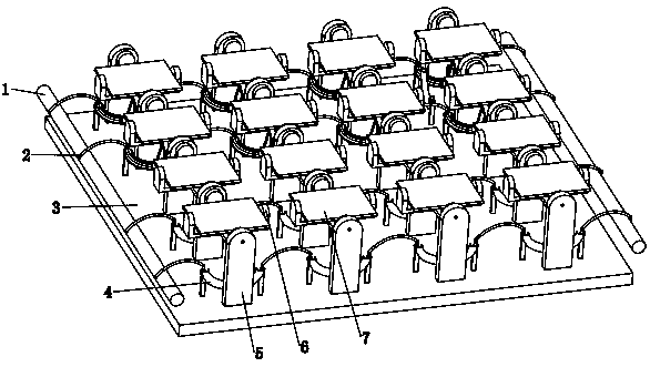
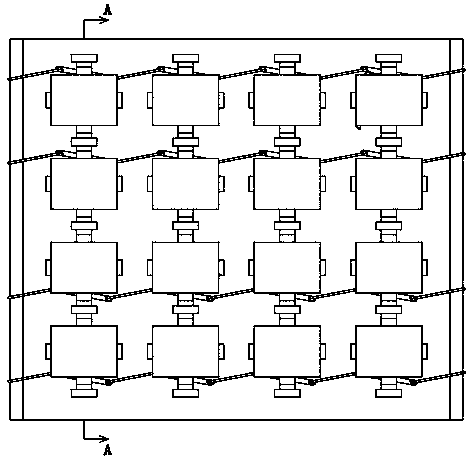
[0039] like Figures 1 to 6 As shown, it is an energy gathering device, including:

[0040] The installation platform 3 and more than one group of installation frames 5; each group of the installation frames 5 is located on the installation platform 3;

[0041] More than one turret 6 and more than one reflector 7; the rotating shaft of each said turret 6 is arranged on the corresponding installation frame 5, and the rotating axis of each said reflector 7 is arranged on the corresponding On the turret 6, the axis of the rotating shaft of the reflector 7 is perpendicular to the axis of the rotating shaft of the turret 6, so that the reflecting mirror 7 can rotate universally on the mounting table 3;

[0042] More than one arc-shaped slide rail 4, more than one connecting rod 9 and more than one slide member 10; each said arc-shaped slide rail 4 is arranged on the installation platform 3, and each said slide member 10 is located on the slide In the corresponding arc-shaped slid...

Embodiment 2

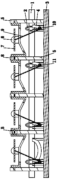
[0057] like Figures 10 to 14 As shown, it is an energy gathering device, including:

[0058] Mounting table 3 and more than one group of mounting frames 5; each group of mounting frames 5 is located on the mounting table 3, and each group of mounting frames 5 is provided with a ball hole 51;

[0059] More than one arc-shaped slide rail 4, more than one connecting rod 9 and more than one slide member 10; each said arc-shaped slide rail 4 is arranged on the installation platform 3, and each said slide member 10 is located on the slide In the corresponding arc-shaped slide rail 4, a universal ball 91 is provided on each of the connecting rods 9, and the universal ball 91 is arranged in the corresponding ball hole 51 and can rotate in the ball hole 51. The two ends of the connecting rod 9 are respectively connected with the slider 10 and the mirror 7 so that the slider 10 drives the mirror 7 to rotate. Different to ensure that the light reflected by each mirror 4 can be reflect...


PUM


Abstract

The invention relates to an energy gathering device which is characterized by comprising a mounting table, mounting frames, rotating frames, reflectors, arc-shaped sliding rails, connecting rods, sliding parts, driving devices and pull ropes, wherein the mounting frames are arranged on the mounting table; the rotating shaft of each rotating frame is rotationally arranged on the corresponding mounting frame, and the rotating shaft of each reflector is rotationally arranged on the corresponding rotating frame; the arc-shaped sliding rails are arranged on the mounting table, the sliding parts arearranged in the arc-shaped sliding rails in a sliding mode, the connecting rods are respectively connected with the sliding parts and the reflectors, and the radians of the arc-shaped sliding rails are different so that the rotating directions of all reflectors are different; the pull ropes are fixedly connected with the sliding parts; and the pull ropes are wound on the corresponding driving devices, and the driving devices pull the pull ropes to move. The energy gathering device has the advantages that the energy gathering effect is good; the reflection angles of the reflectors can be adjusted and controlled according to different sun irradiation angles, and the shapes of the arc-shaped sliding rails are easy to determine, thereby realizing driving linkage of the reflectors; and batch production can be realized.

Description

technical field [0001] The invention relates to an energy gathering device. Background technique [0002] At present, the energy gathering device includes a planar structure and a plurality of reflectors, and the plurality of reflectors are installed on the planar structure. When working, the rotation of the east-west angle of the sun is tracked through the planar structure, so that each reflector has a fixed trajectory when tracking the sun's pitch angle; however, during the tracking process, each reflector has a different two-dimensional rotation and rotational speed, which is difficult to control. [0003] In addition, U.S. Patent No. US6820611B2 discloses the moving components and guiding components in the light concentrating method device, which are single-piece processed products, and it is difficult to manufacture them in batches. Contents of the invention [0004] The purpose of the present invention is to overcome the deficiencies of the prior art and provide an ...

Claims


Application Information

Patent Timeline
Patent Type & Authority Applications(China)
IPC IPC(8): G02B7/182
CPCG02B7/1821F24S23/77F24S50/20F24S30/455F24S2030/137F24S2030/133F24S2030/136F24S2030/145F24S30/42
Inventor 梁卫民
Owner ASIA PACIFIC MEGA TRADE LTD
Why Eureka
Try Eureka