Method and device for processing channel state information reference signal

A channel state information and reference signal technology, applied in the field of communication, can solve the problems of high calculation judgment and implementation overhead, different delivery methods, cumbersome calculations, etc., to avoid complex and repeated calculations, reduce the number of complex calculations, and improve processing efficiency effect

Active Publication Date: 2021-04-27
SANECHIPS TECH CO LTD
View PDF7 Cites 0 Cited by
  • Summary
  • Abstract
  • Description
  • Claims
  • Application Information

AI Technical Summary

Problems solved by technology

[0012] Among them, since the paging signal is decoded by SIB2 and sent to the physical layer through signaling by the upper layer, the resource location may not be unique, and the resource configuration parameters of zero-power CSI-RS and non-zero-power CSI-RS are sent The method is different, so that the non-zero power CSI-RS can only determine the resource configuration index after the bitmap (Bitmap) is reversed; in addition, when the zero-power CSI-RS and the non-zero-power CSI-RS exist in the same subframe, it is possible Conflicts also occur. At this time, the conditions that need to be considered and judged are doubled, resulting in high computational judgment and implementation overhead
[0013] In addition, in an LTE-based UE system, the channel estimation module, PDSCH decoding module, and channel quality information feedback module all need to use some or all of the CSI-RS related parameters. The calculation of the individual CSI-RS parameters used in this module also needs to complete the complex calculation and judgment of the real subframe and time-frequency resources where the CSI-RS is located. At the same time, each software and hardware module has different hardware processing timings each time. Each module needs to be calculated separately, which can easily lead to timing coordination problems. Based on the above reasons, the existing design may involve the calculation of a large amount of CSI-RS position and other related data, resulting in cumbersome calculations, large amounts of calculations, tight timing and eventually lead to decoding problem

Method used


Image

  • Method and device for processing channel state information reference signal
  • Method and device for processing channel state information reference signal
  • Method and device for processing channel state information reference signal

Examples


Embodiment 1

[0068] Such as figure 1 As shown, the implementation process of the CSI-RS processing method in the embodiment of the present invention includes the following steps:

[0069] Step 101: Detect whether CSI-RS is enabled and whether configuration parameters of CSI-RS have changed, wherein the CSI-RS includes zero-power CSI-RS and non-zero-power CSI-RS;

[0070] Here, the configuration parameters of the CSI-RS include: resource configuration parameters and subframe configuration parameters.

[0071] Here, by detecting the data related to the configuration parameters of the CSI-RS delivered by the high-level signaling, the configuration parameters of the CSI-RS delivered this time are saved, and are compared with the configuration parameters of the CSI-RS previously delivered by the high-level signaling. By comparison, it is judged whether the configuration parameters of the CSI-RS delivered by the high layer signaling this time have changed.

[0072] It should be noted that if t...

Embodiment 2

[0086] The specific implementation process of the CSI-RS processing method in the embodiment of the present invention will be further described in detail below.

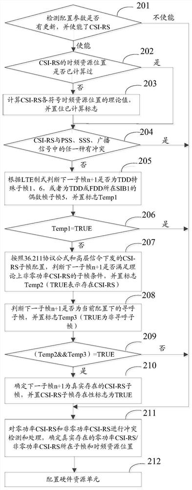
[0087] figure 2 A schematic diagram of a specific implementation flow chart of the CSI-RS processing method in the embodiment of the present invention is given, as shown in figure 2 shown, including the following steps:

[0088] Step 201: Detect the data related to the configuration parameters of the CSI-RS delivered by high-level signaling, save the configuration parameters of the CSI-RS delivered this time, and compare them with the configuration parameters of the CSI-RS delivered last time, If CSI-RS is enabled, and the configuration parameters of CSI-RS have changed, then perform the next step; if CSI-RS is not enabled, then jump to step 211; if CSI-RS is enabled, but the configuration of CSI-RS If there is no change in the parameters, go to the next step;

[0089] Here, if the CSI-RS is enabled, but the con...

Embodiment 3

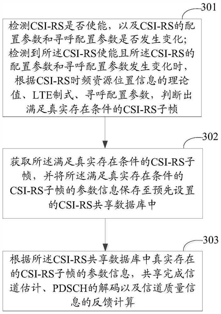
[0115] image 3 A schematic flowchart of another CSI-RS processing method according to an embodiment of the present invention is given, as shown in image 3 shown, including the following steps:

[0116] Step 301: Detect whether the CSI-RS is enabled, and whether the CSI-RS configuration parameters and paging configuration parameters have changed; detect that the CSI-RS is enabled and the CSI-RS configuration parameters and paging configuration parameters When a change occurs, according to the theoretical value of the CSI-RS time-frequency resource location information, the LTE standard, and the paging configuration parameters, determine the CSI-RS subframe that meets the real existence conditions;

[0117] Here, according to the theoretical value of the CSI-RS time-frequency resource location information, the LTE standard, and the paging configuration parameters, the CSI-RS subframe that satisfies the real existence condition is determined, including:

[0118] According to ...


PUM


Abstract

The invention discloses a channel state information reference signal (CSI-RS) processing method, including: detecting whether the CSI-RS is enabled and whether the configuration parameters of the CSI-RS are changed, wherein the CSI-RS includes zero-power CSI -RS and non-zero-power CSI-RS; when it is detected that the CSI-RS is enabled and the configuration parameters of the CSI-RS change, according to the theoretical value of the CSI-RS time-frequency resource location information, the long-term evolution (LTE) System, paging configuration parameters, determine the CSI-RS subframe that meets the real existence condition; perform collision processing on the zero-power CSI-RS and non-zero-power CSI-RS in the real CSI-RS subframe. The invention also discloses a CSI-RS processing device at the same time.

Description

technical field [0001] The present invention relates to signal processing technology in the field of communication, in particular to a method and device for processing Channel State Information Reference Signal (CSI-RS, Channel State Information Reference Signal). Background technique [0002] In the Long Term Evolution (LTE, Long Term Evolution) / Long Term Evolution Advanced (LTE-A, Long Term Evolution Advanced) system, for the evolved base station (eNB, Evolved NodeB), after layer mapping and precoding are completed, the physical The downlink shared channel (PDSCH, Physical Downlink Shared Channel) is mapped to the resource element (RE, Resource Element); among them, the RE is the basic unit of resource scheduling of the downlink physical channel on the LTE / LTE-A system, and the RE is composed of One Orthogonal Frequency Division Multiplexing (OFDM, Orthogonal Frequency Division Multiplexing) symbol and one subcarrier in the frequency domain. Therefore, generally speaking,...

Claims


Application Information

Patent Timeline
Patent Type & Authority Patents(China)
IPC IPC(8): H04W24/02H04W72/04H04L5/00
CPCH04L5/0048H04W24/02H04W72/20
Inventor 朱超
Owner SANECHIPS TECH CO LTD
Why Eureka
Try Eureka