
Grounding transfer wire clamp and wire grounding structure

A grounding structure and transfer wire technology, applied in connection, conductive connection, electrical component connection, etc., can solve problems such as increased production cost, uneven distribution of electric field at grounding position, and inconvenient wiring.

Inactive Publication Date: 2018-10-23
GUANGZHOU POWER SUPPLY CO LTD
View PDF6 Cites 1 Cited by
  • Summary
  • Abstract
  • Description
  • Claims
  • Application Information

AI Technical Summary

Problems solved by technology

When the grounding is suspended, the operator needs to lift the grounding wire for a long time, which is prone to fatigue, resulting in low efficiency of the grounding operation; when the suspended position of the wire is high, it needs to use a high-altitude vehicle to operate, which increases the production cost; when the grounding wire is connected, the joint faces a single , which brings inconvenience to the wiring; in addition, the uneven distribution of the electric field at the grounding position is likely to cause accidents

Method used


Image

  • Grounding transfer wire clamp and wire grounding structure
  • Grounding transfer wire clamp and wire grounding structure
  • Grounding transfer wire clamp and wire grounding structure

Examples


Embodiment Construction

[0027] Embodiments of the present invention are described in detail below in conjunction with accompanying drawings:

[0028] It should be noted that when an element is “fixed” to another element, it may be directly on the other element or there may be an intervening element. When an element is referred to as being "connected to" another element, it can be directly connected to the other element or intervening elements may also be present. In contrast, when an element is referred to as being "directly on" another element, there are no intervening elements present. The terms "vertical," "horizontal," "left," "right," and similar expressions are used herein for purposes of illustration only and are not intended to represent the only embodiments.

[0029] Unless otherwise defined, all technical and scientific terms used herein have the same meaning as commonly understood by one of ordinary skill in the technical field of the invention. The terminology used herein in the descrip...


PUM


Abstract

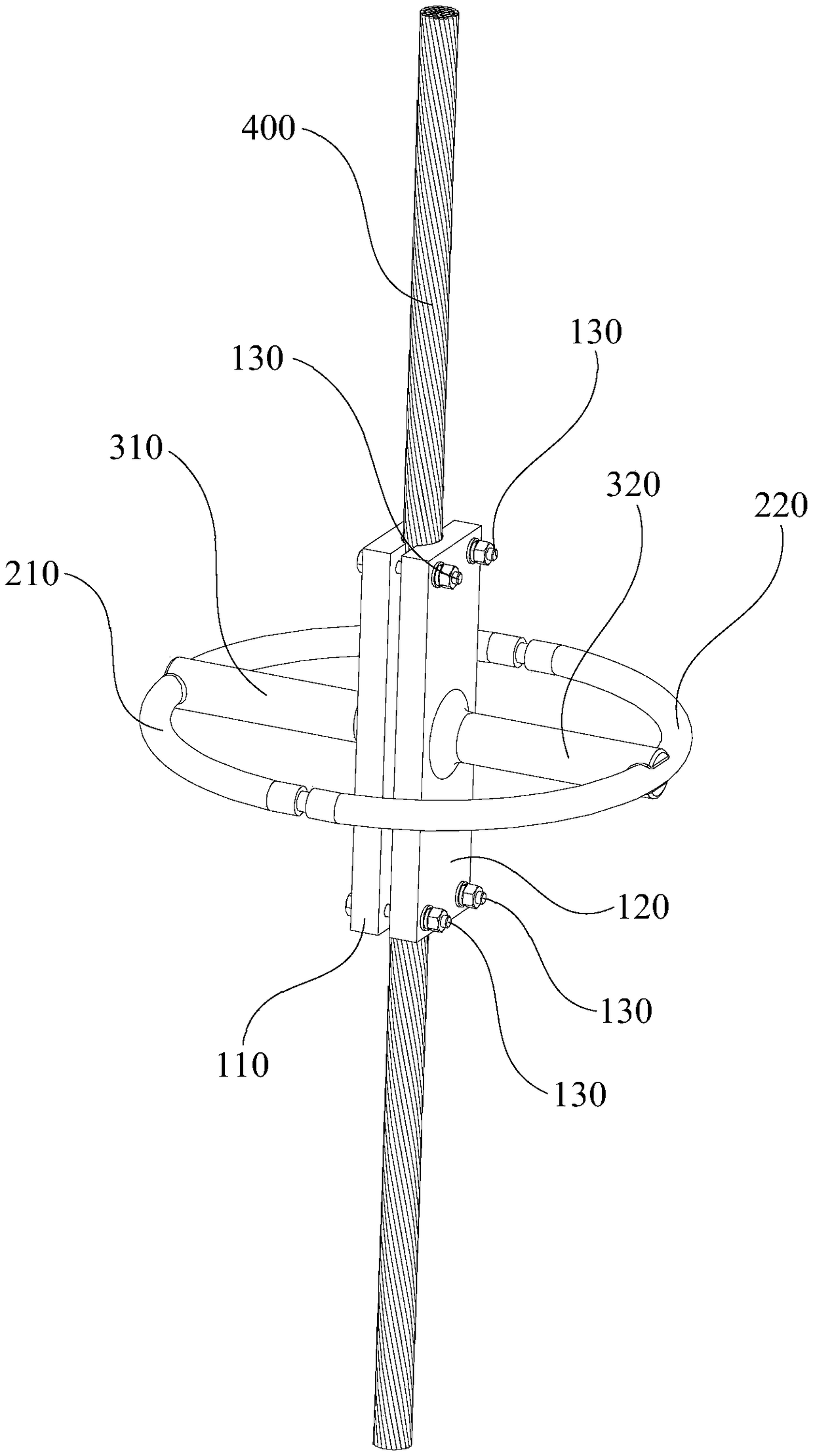
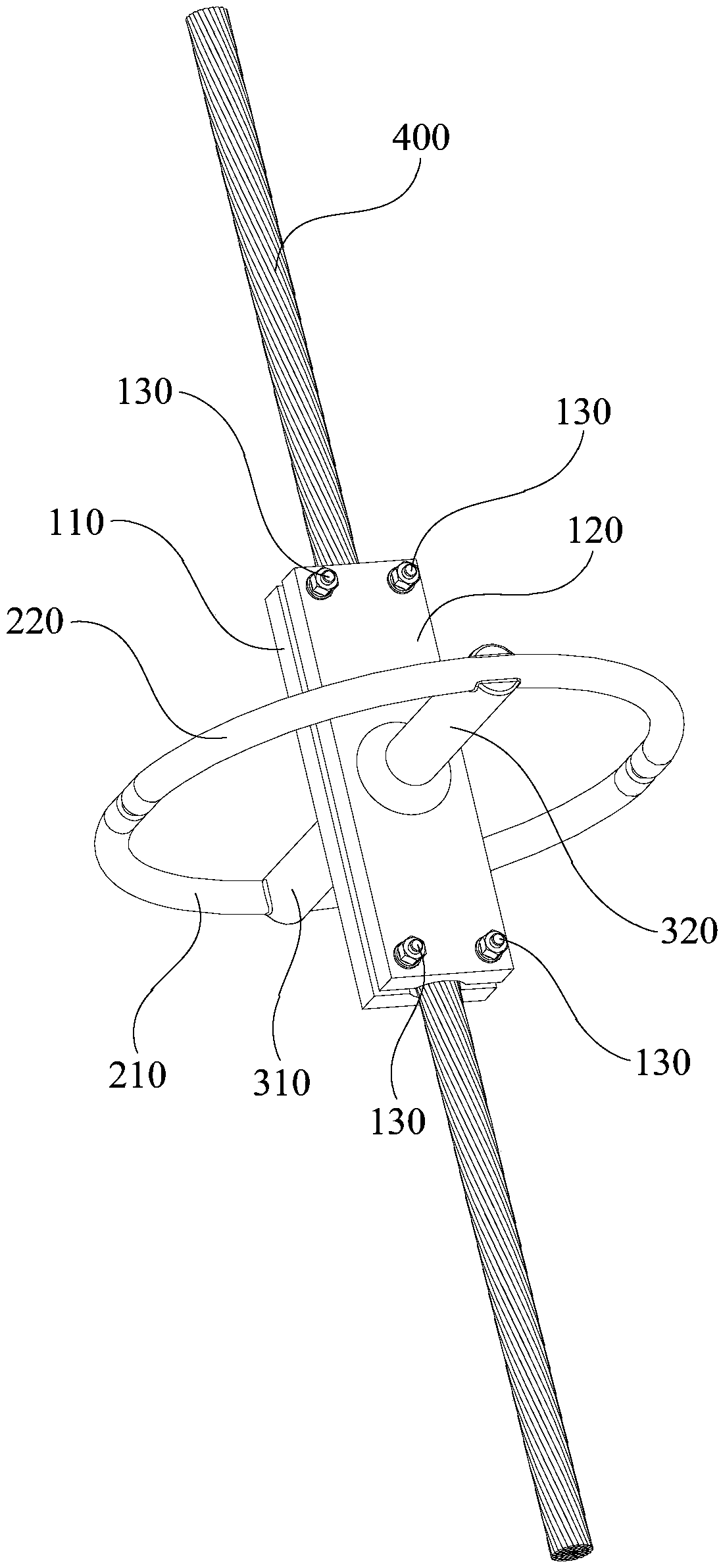
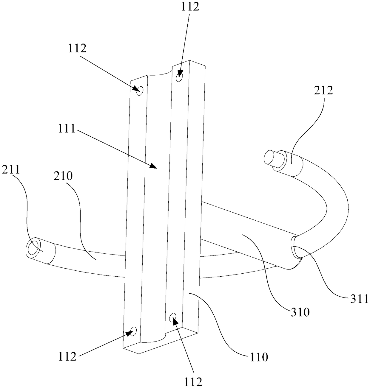
The invention relates to a grounding transfer wire clamp and a wire grounding structure. The grounding transfer wire clamp comprises a clamping mechanism, an erecting mechanism and a mounting mechanism, wherein the clamping mechanism is used for clamping a wire; the erecting mechanism comprises an erecting ring, and the erecting ring sleeves the periphery of the wire and is used for erecting of agrounding wire; and the mounting mechanism is used for mounting the erecting ring on the clamping mechanism and can enable the erecting ring and the clamping mechanism to be conducted. The wire grounding structure comprises a wire, a grounding wire and a grounding transfer wire clamp. Due to the arrangement of the erecting ring, when the wire needs to be grounded, the clamping mechanism clamps thewire, one end of the grounding wire is erected on the erecting ring, grounding operation of the wire is realized, the structure is simple, the operation is convenient, and the grounding efficiency ishigh; due to the arrangement of the annular erecting ring, an electric field at the grounding position is uniformly distributed along the annular erecting ring, grounding is ensured to be safe and reliable, the grounding wire can be erected from multiple angles due to the annular erecting ring, and the erecting position selection perplexity brought by limitation of the grounding space can be avoided.

Description

technical field [0001] The invention relates to the technical field of grounding structures, in particular to a grounding transfer clip and a wire grounding structure. Background technique [0002] When high-voltage primary equipment is powered off for maintenance, reliable grounding of its wires is an important measure to ensure the safety of maintenance personnel. Therefore, it is very important to ensure that the conductor can be reliably grounded. [0003] In the actual maintenance process, different wires have various forms and different positions. When the grounding is suspended, the operator needs to lift the grounding wire for a long time, which is prone to fatigue, resulting in low efficiency of the grounding operation; when the suspended position of the wire is high, it needs to use a high-altitude vehicle to operate, which increases the production cost; when the grounding wire is connected, the joint faces a single , which brings inconvenience to the wiring; in ...

Claims


Application Information

Patent Timeline
IPC IPC(8): H01R11/12
CPCH01R11/12
Inventor 朱信红刘威葳陈宇昇蒋健石剑华冯玉辉黄智聪李果刘剑锋陈小龙方俊钦罗子越黎旭陈兴华杨鹏黄国强陈丽萍
Owner GUANGZHOU POWER SUPPLY CO LTD
Learn More