Coupling joint for plane joint robot and manufacturing equipment for coupling joint

A technology of planar joints and manufacturing equipment, which is applied in the field of robotics, can solve problems such as poor heavy load bearing capacity, increased manufacturing cost and maintenance cost, unfavorable expansion of the rotation axis, etc., to achieve good self-adaptive adjustment and support capabilities, and to improve The effect of carrying capacity

Pending Publication Date: 2018-10-26
常州市知豆信息科技有限公司
View PDF0 Cites 2 Cited by
  • Summary
  • Abstract
  • Description
  • Claims
  • Application Information

AI Technical Summary

Problems solved by technology

The more joints of the rotary axis of the robot, the larger the space and range of its operation, but at this time, the self-weight of the fully extended end and the torque or other loads required for operation will cause a serious burden on the joints of the rotary axis, so The higher the accuracy of assembly, the strength of materials, and other processing requirements, it will greatly increase the cost of manufacturing and subsequent maintenance, and it is also not conducive to the expansion of more rotating shafts.
At the same time, in the daily use of planar joint robots, they are generally used for loading objects, which need to withstand certain shocks and vibrations. The traditional robot joint structure is not good at bearing heavy loads, and it is an extremely important issue for the rigidity of the entire mechanical mechanism. big challenge

Method used


Image

  • Coupling joint for plane joint robot and manufacturing equipment for coupling joint
  • Coupling joint for plane joint robot and manufacturing equipment for coupling joint
  • Coupling joint for plane joint robot and manufacturing equipment for coupling joint

Examples


Embodiment Construction

[0031] The present invention is described in further detail now in conjunction with accompanying drawing. These drawings are all simplified schematic diagrams, which only illustrate the basic structure of the present invention in a schematic manner, so they only show the configurations related to the present invention.

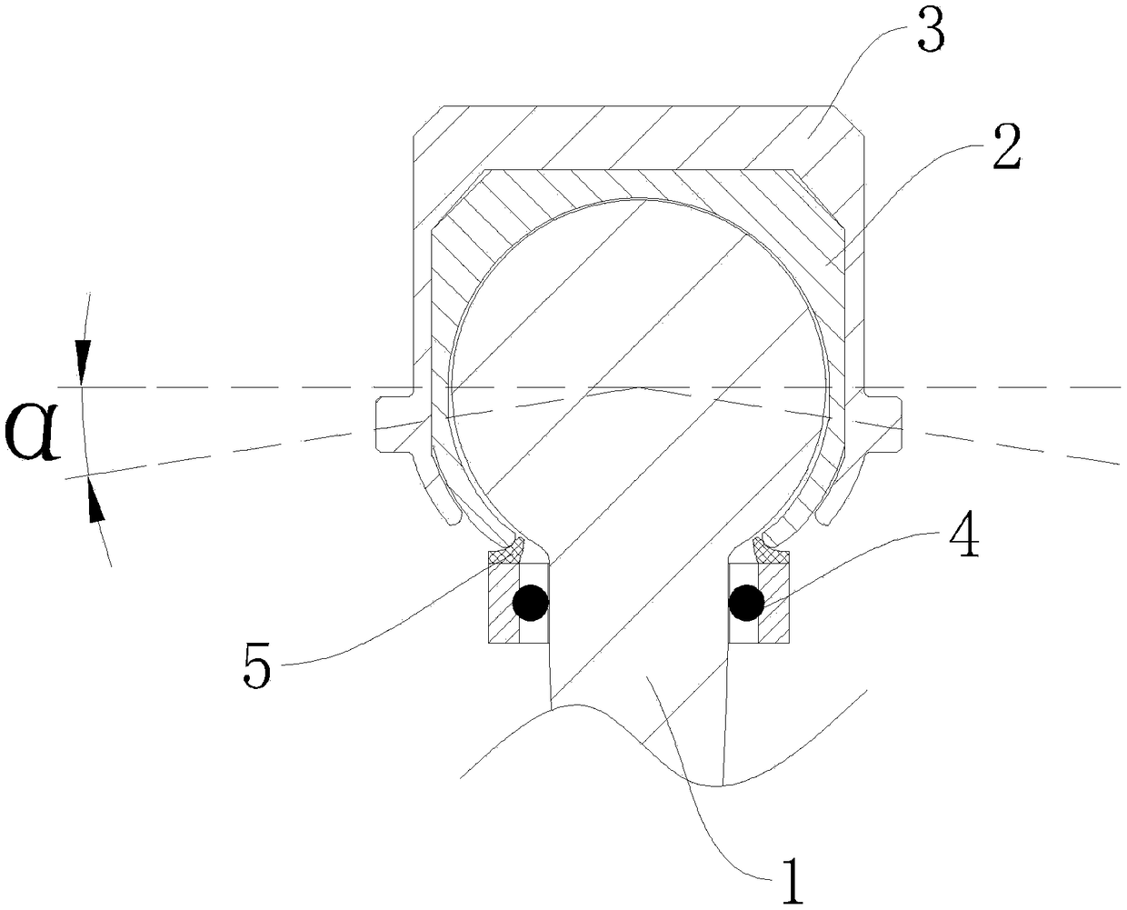
[0032] Such as figure 1 The shown embodiment of a coupling joint for a planar joint robot of the present invention has a connecting cylinder 1, the upper end of the connecting cylinder 1 is in the shape of a ball head, and the lower end is in the shape of a cylinder, and the lower end of the cylinder can be directly set as a stud The upper end of the connecting cylinder 1 is in the shape of a ball head, and the lubricating sleeve 2 and the connecting housing 3 are arranged in sequence from the inside to the outside. grinding layer, and the lower end of the lubricating sleeve 2 covers the upper end of the connecting cylinder 1, the ball end of the entire conne...


PUM


Abstract

The invention relates to a coupling joint for a plane joint robot and manufacturing equipment for the coupling joint. The coupling joint is provided with a connecting column body. The upper end of theconnecting column body is in a bulb shape, and the lower end of the connecting column body is in a column shape. A lubricating sleeve and a connecting shell are arranged at the outer side of the bulb-shaped portion of the upper end of the connecting column body in sequence from inside to outside. The manufacturing equipment is provided with an initial station, a filling device A, a lubricating oil application device, a filling device B, an extruding device and a separating device, wherein the initial station is used for allowing the connecting shell to be placed thereon; the filling device Ais used for allowing the lubricating sleeve to be mounted thereon; and the filling device B is used for allowing the connecting column body to be mounted thereon. By means of the coupling joint, the traditional design of similar bearing structures is changed; the wear resistance and lubrication effects of a graphene coating are fully utilized; the bearing capacity in the vertical direction can beremarkably increased on the basis of structure simplification; meanwhile, the better self-adaptive adjustment and support capacities are achieved in the horizontal plane direction, and the extremely high practical value is achieved; and meanwhile, the manufacturing equipment for the coupling joint is efficient, convenient and fast to use, and the whole coupling joint can be implemented conveniently.

Description

technical field [0001] The invention relates to the technical field of robots, in particular to a coupling joint for a planar joint robot and manufacturing equipment thereof. Background technique [0002] In the known technical field, a planar articulated robot generally has at least three rotation axes parallel to each other, and the cross sections of the rotation axes are parallel to each other. The main application areas are loading, unloading, welding, packaging, fixing, coating, painting, bonding, packaging, special handling operations, assembly, etc. The more joints of the rotary axis of the robot, the larger the space and range of its operation, but at this time, the self-weight of all the extended ends and the torque or other loads required for operation will cause serious burdens on the joints of the rotary axis, so The higher the accuracy of assembly, the strength of materials, and other processing requirements, it will greatly increase the cost of manufacturing a...

Claims


Application Information

Patent Timeline
Patent Type & Authority Applications(China)
IPC IPC(8): B25J17/00B23P21/00B23P19/00
CPCB25J17/00B23P19/001B23P21/002
Inventor 张夕林
Owner 常州市知豆信息科技有限公司
Why Eureka
Try Eureka