Eureka AIR delivers breakthrough ideas for toughest innovation challenges, trusted by R&D personnel around the world.

Key switch with pressing balance function

A technology of balance function and button, which is applied in the direction of electric switches, key modules, contact operation parts, etc., can solve problems such as uneven pressing, loose structural fit, uncoordinated interaction, etc., so as to improve the pressing balance force and structural effect Coordinate and improve the effect of pressing

Pending Publication Date: 2018-11-06
DONGGUAN CITY KAIHUA ELECTRONICS
View PDF0 Cites 3 Cited by
  • Summary
  • Abstract
  • Description
  • Claims
  • Application Information

AI Technical Summary

Problems solved by technology

[0002] Many operations of existing devices require the use of key switches as input means. The quality of the key switch determines the experience of the input device. It is necessary to ensure a good feel and service life. At the same time, the stability during use also has high requirements. There can be no stuck corners, and these technical problems are in the process of continuous improvement, but they are still not ideal
[0003] During the pressing process of the existing key switch, especially when pressing the corners, due to structural limitations, the internal structures are not closely matched, the interaction is uncoordinated, the balance is poor, the pressing is not stable, and the stability is poor, often appearing. Astringent feeling, unsmooth use, affecting normal use, and pressing feel

Method used


Image

  • Key switch with pressing balance function
  • Key switch with pressing balance function
  • Key switch with pressing balance function

Examples


Embodiment 1

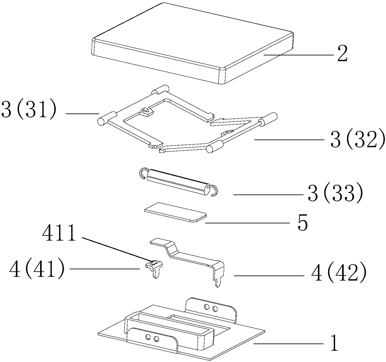
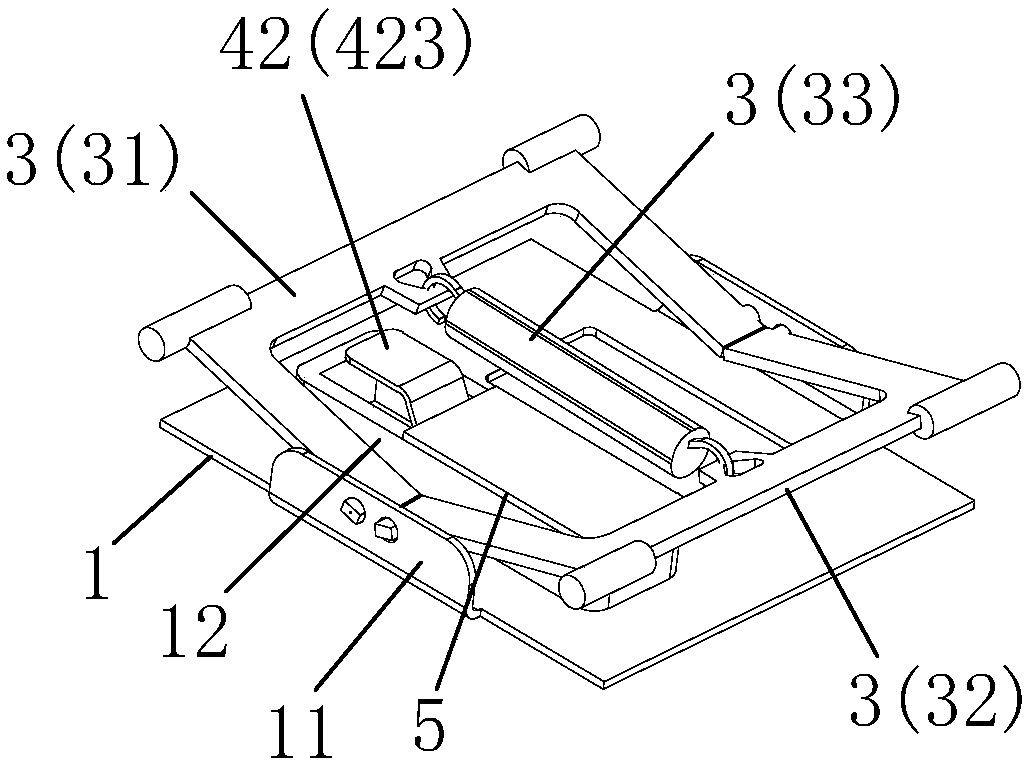
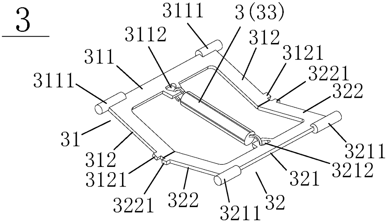
[0037] Please refer to figure 1 , figure 2 and Figure 8 , the present embodiment provides a key switch with a press balance function, including a base 1, a keycap 2 disposed above the base 1, and a press balance assembly 3 disposed between the base 1 and the keycap 2, wherein , the pressing balance assembly 3 includes a balance frame A 31 connected between the base 1 and the keycap 2, a balance frame B 32 connected between the base 1 and the keycap 2, and a balance frame B 32 connected between the balance frame A 31 and the balance An elastic body between the brackets B 32 , preferably, the elastic body is a tension spring 33 .

[0038] In the process of pressing and conducting the key switch, no matter which position on the keycap 2 is pressed, the combination of the balance frame A 31 and the balance frame B 32 swings up and down to offset the component force of the pressing force in the inclined direction, so that the key is stressed Balanced to improve the overall pre...

Embodiment 2

[0046] The main difference between this embodiment and Embodiment 1 is that this embodiment uses a photoelectric conduction method to realize the conduction and disconnection functions of the key switch, and the specific structure of the conduction component 4 is different. Correspondingly, the base 1 and the The corresponding structures on the keycap 2 are also different, but the specific structure of the pressing balance assembly 3 is the same. Specifically, such as Figure 9 to Figure 13 As shown, the lower end of the base 1 is provided with a PCB board 6, and the conduction component 4 includes a photoelectric emitting tube 41' and a photoelectric receiving tube 42' respectively arranged on the PCB board 6 and embedded in the base; The lower end of the keycap 2 is provided with a protrusion 22 extending downwards, such as Figure 11 shown.

[0047] At the same time, if Figure 10 , Figure 12 and Figure 13 As shown, a pedestal 13 is protruded upward on the upper end ...


PUM


Abstract

The invention discloses a key switch with a pressing balance function. The key switch comprises a base, a key cap arranged above the base and a pressing balance assembly arranged between the base andthe key cap, wherein the pressing balance assembly comprises a balance rack A connected between the base and the key cap, a balance rack B connected between the base and the key cap and an elastomer connected between the balance rack A and the balance rack B. The key switch provided by the invention has good pressing balance and stability, the pressing stroke is obviously increased, and the pressing hand feeling is improved.

Description

technical field [0001] The invention relates to a key switch, in particular to a key switch with pressing balance function. Background technique [0002] Many operations of existing devices require the use of key switches as input means. The quality of the key switch determines the experience of the input device. It is necessary to ensure a good feel and service life. At the same time, the stability during use also has high requirements. There should be no stuck corners, and these technical problems are in the process of continuous improvement, but they are still not ideal. [0003] During the pressing process of the existing key switch, especially when pressing the corners, due to structural limitations, the internal structures are not closely matched, the interaction is uncoordinated, the balance is poor, the pressing is not stable, and the stability is poor, often appearing. Astringent feeling, unsmooth use, affecting normal use, and pressing feel. Contents of the inve...

Claims


Application Information

Patent Timeline
Patent Type & Authority Applications(China)
IPC IPC(8): H01H3/12
CPCH01H3/125H01H13/705H01H13/10H01H13/14H01H13/20H01H2233/07
Inventor 吴福喜吕攀豪
Owner DONGGUAN CITY KAIHUA ELECTRONICS
Why Eureka
Eureka Blog
Learn More