


Quick Research
Generate reliable direction feasibility study reports for your R&D in just a few steps.

Technical Q&A
Discover and master advanced knowledge NOW. Basics, ideas, possibilities, all at once.

Find Solutions
As an expert in R&D theories, this can generate solutions to your technical problems instantly.

Evaluate Feasibility
Analyze your overall solution with one click, know your potential R&D risks in advance.

Monitor Landscape
Get weekly tech updates, stay abreast of the latest tech innovations and key insights.
Injection molding machine
A technology for injection molding machines and injection devices, which is applied in the field of injection molding machines, can solve problems such as screw skew, and achieve the effect of shortening the front and rear dimensions
- Summary
- Abstract
- Description
- Claims
- Application Information
AI Technical Summary
Problems solved by technology
Method used
Image


Examples
no. 1 Embodiment approach
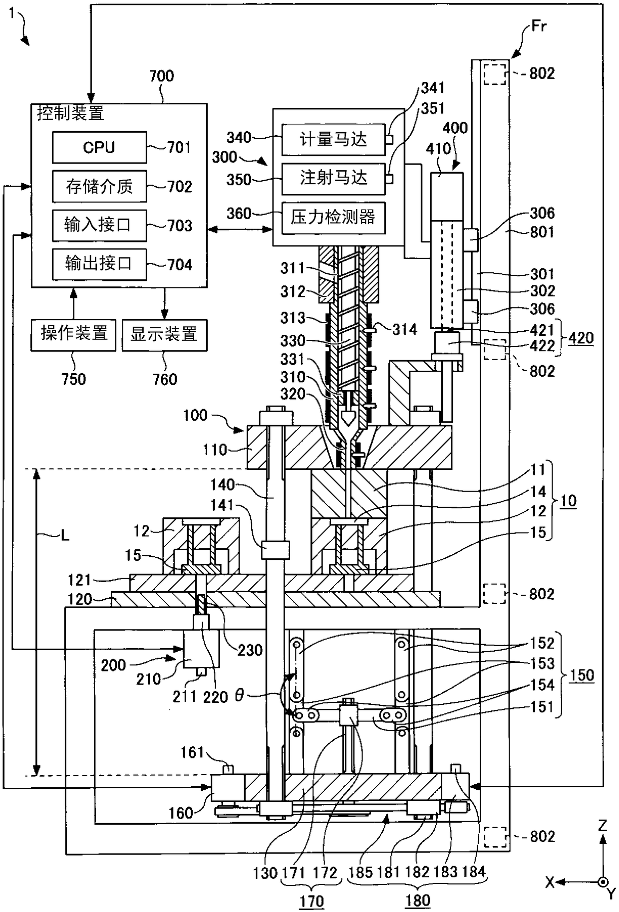
[0022] refer to Figure 1 ~ Figure 4 , and the first embodiment will be described. In addition, in Figure 1 ~ Figure 4 Among them, the X direction, the Y direction, and the Z direction are directions perpendicular to each other. The X direction and the Y direction are horizontal directions, and the Z direction is a vertical direction. The X direction is the front-back direction of the vertical injection molding machine 1 (hereinafter also referred to as "injection molding machine 1") according to the first embodiment, figure 1 The left side (the side of the ejector device 200) is the front side, and the right side (the column portion 801 side of the frame Fr) is the rear side. The Y direction is the width direction of the injection molding machine 1 . The Z direction is the up and down direction, figure 1 The upper side of is vertically above, and the lower side is vertically below.
[0023] and, in figure 1 and figure 2 In the figure, for convenience of description,...
no. 2 Embodiment approach
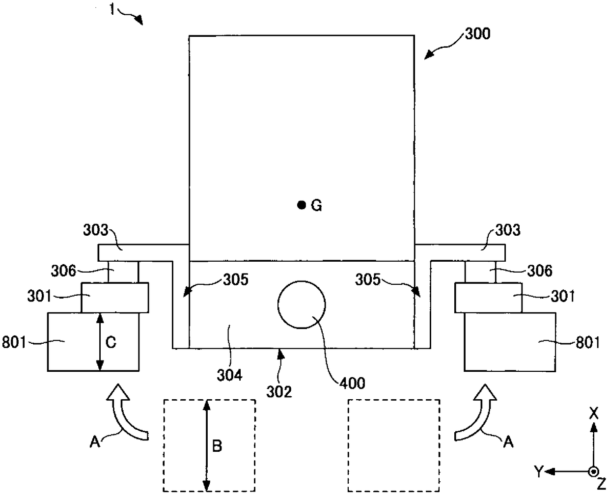
[0116] refer to Figure 5 , and the second embodiment will be described. Figure 5 It is a plan view showing the positional relationship between the injection device 300 and the frame Fr in the injection molding machine 1A according to the second embodiment.
[0117] like Figure 5 As shown, the pair of protrusions 303A, 303A of the injection device 300 and the pair of guides 301A, 301A provided on the pair of pillars 801, 801 of the frame Fr are connected behind the pair of pillars 801, 801 of the frame Fr. In this respect, the injection molding machine 1A of the second embodiment is different from the injection molding machine 1 of the first embodiment.
[0118] The injection device 300 includes a pair of protrusions 303A, 303A protruding on both sides in the width direction of the injection device 300 at the rear end of the injection device 300 and facing the rear surfaces of the pair of column parts 801 , 801 of the frame Fr. More specifically, the slider 302 of the inj...
no. 3 Embodiment approach
[0125] refer to Image 6 , and the third embodiment will be described. Image 6 It is a plan view showing the positional relationship between the injection device 300 and the frame Fr in the injection molding machine 1B according to the third embodiment.
[0126] like Image 6 As shown, the injection molding machine 1B of the third embodiment differs from the injection molding machine 1 of the first embodiment in that a pair of frame side protrusions 303B, 303B are provided on a pair of column parts 801, 801 of the frame Fr.
[0127] The frame Fr includes a pair of frame-side protrusions 303B, 303B protruding toward the center side on opposing surfaces of the pair of column parts 801 , 801 and facing the rear of the injection device 300 . The pair of guides 301B, 301B are respectively provided on the front side of the pair of frame side protrusions 303B, 303B. The injection device 300 is coupled to a pair of guides 301B, 301B via a slider 306 provided at the rear of the inj...
PUM
 Abstract
Description
Claims
Application Information
 - R&D Engineer
- R&D Manager
- IP Professional
- Industry Leading Data Capabilities
- Powerful AI technology
- Patent DNA Extraction
Browse by: Latest US Patents, China's latest patents, Technical Efficacy Thesaurus, Application Domain, Technology Topic, Popular Technical Reports.
© 2024 PatSnap. All rights reserved.Legal|Privacy policy|Modern Slavery Act Transparency Statement|Sitemap|About US| Contact US: help@patsnap.com