Gate drive circuit, drive method thereof, and display device

A gate drive circuit and gate drive technology, applied to static indicators, instruments, etc., can solve problems such as inability to achieve retrace

Inactive Publication Date: 2018-11-23
BOE TECH GRP CO LTD +1
View PDF8 Cites 3 Cited by
  • Summary
  • Abstract
  • Description
  • Claims
  • Application Information

AI Technical Summary

Problems solved by technology

The existing gate drive circuit can only scan sequentially, and cannot realize retrace, that is, after scanning from

Method used


Image

  • Gate drive circuit, drive method thereof, and display device
  • Gate drive circuit, drive method thereof, and display device
  • Gate drive circuit, drive method thereof, and display device

Examples


Embodiment 1

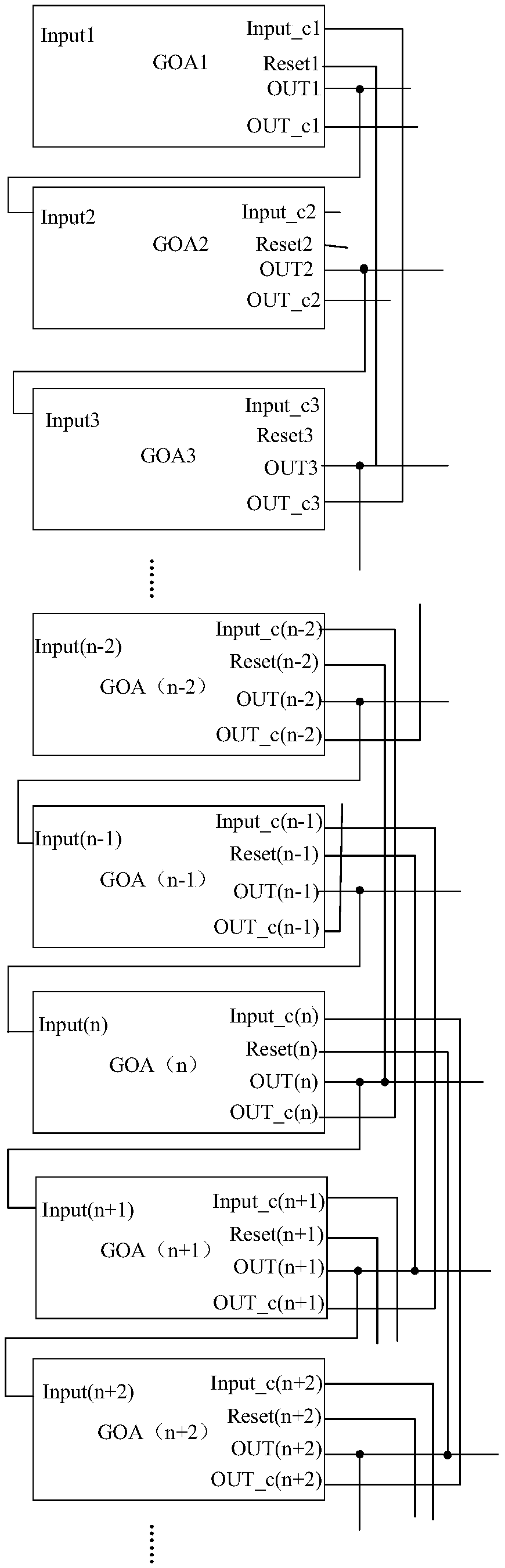
[0035] figure 1 is a schematic diagram of the overall structure of the gate drive circuit provided in Embodiment 1 of the present invention,

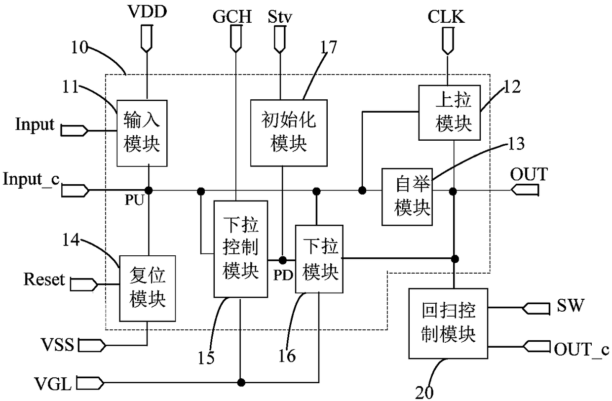
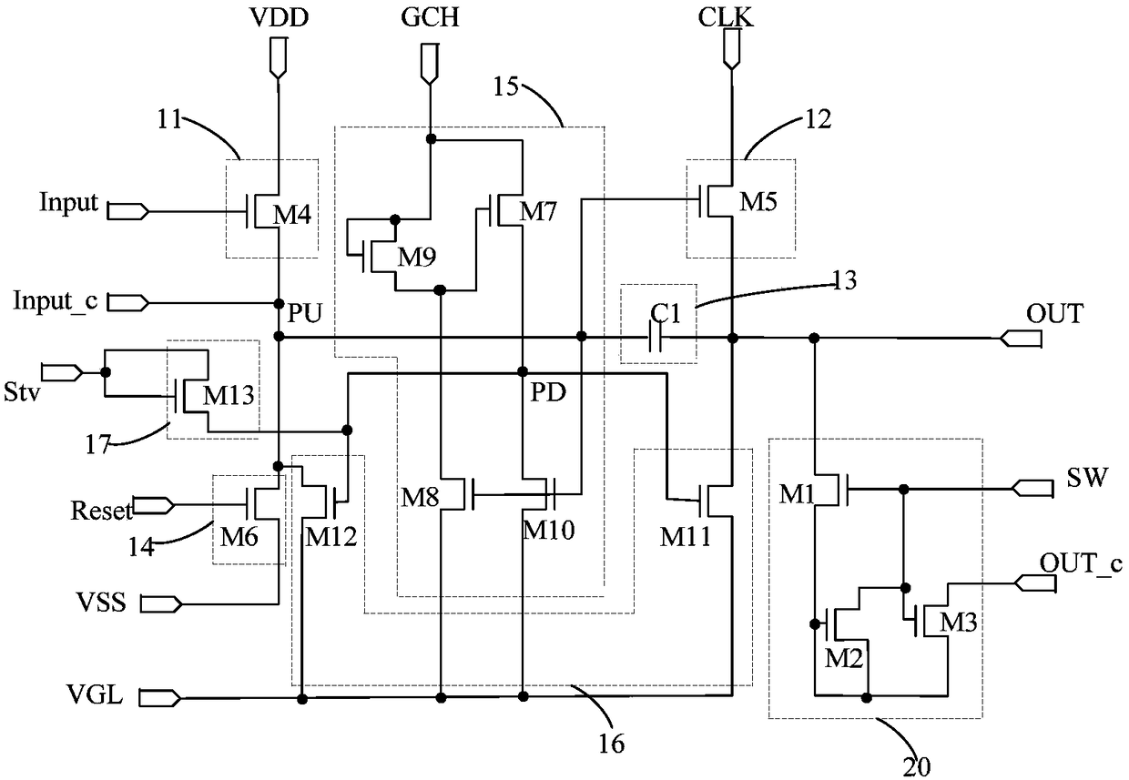
[0036] figure 2 is a schematic diagram of the module structure of the gate driving unit in Embodiment 1 of the present invention, image 3 It is a schematic diagram of the specific structure of the gate driving unit provided in Embodiment 1 of the present invention. combine figure 1 and figure 2 As shown, the gate drive circuit includes a plurality of cascaded gate drive units (such as figure 1 GOA1, GOA2...), the gate drive unit includes a shift register 10 and a retrace control module 20 . in:

[0037] In two adjacent gate drive units, the output terminal OUT of the shift register 10 in the upper gate drive unit is connected to the input terminal Input of the shift register OUT in the next gate drive unit, and the shift register 10 When the pull-up node PU is at an effective potential, the clock signal terminal CLK and the ou...

Embodiment 2

[0068] Embodiment 2 of the present invention provides a driving method for the above-mentioned gate driving circuit. The gate driving circuit can be used in a touch display device, and display scanning and touch scanning are performed alternately. The working mode is: in the first In the first display stage, the input terminals of the shift registers in the first n stages of gate driving units sequentially receive valid signals, thereby sequentially outputting valid signals. After that, in the touch stage, the touch driving signals are sequentially output to each touch driving electrode, and each shift register stops outputting valid signals. Afterwards, in the second display stage, effective signals are sequentially output from the shift register of the n-2th level (or other levels before the nth level) gate driving unit until the last level of gate driving unit. Then, touch scanning is performed, and so on. The driving method includes:

[0069] In the display stage, the cl...

Embodiment 3

[0074] The third embodiment provides a display device, including the above-mentioned gate driving circuit and an array substrate. The array substrate includes a plurality of gate lines, and the gate lines are connected to the output terminals of the shift register of the gate driving unit one by one. Correspondingly connected.

[0075] The display device also includes a timing control module, which is used to provide the flyback control terminal of each gate drive unit with Invalid signal: in the pull-up sub-phase of the shift register of the gate driving unit driven at the last stage in the display phase, a valid signal is provided for the flyback control terminal of each gate driving unit. The timing control module can also provide valid signals for each flyback control terminal during the touch stage, and provide invalid signals for the clock terminals of the shift registers of each gate drive unit.

[0076] When the display device of the present invention is working, one ...


PUM


Abstract

The invention provides a gate drive circuit, and the circuit comprises a plurality of cascaded gate drive units. Each gate drive unit includes a shift register. In two adjacent gate drive units, an output end of the shift register at the former stage is connected with an input end of the shift register at the next stage. When a pull-up node of each shift register is at an effective potential, a clock signal end and the output end of the shift register are turned on. Each gate drive unit further includes a flyback control module which is connected with a flyback control terminal and the outputend of the corresponding shift register and is used for outputting a valid signal when the flyback control terminal receives the valid signal and the output end of the shift register outputs the validsignal. In the gate drive units of the continuous m stages, the output end of the flyback control module at the last stage is connected with the pull-up node of the shift register at the first stage,wherein m is an integer greater than one and less than the total number of gate drive units. The present invention also provides a drive method for the gate drive circuit and a display device. The gate drive circuit is capable of implementing flyback.

Description

technical field [0001] The present invention relates to the field of display technology, in particular to a gate driving circuit, a driving method thereof, and a display device. Background technique [0002] Gate Driver On Array (GOA for short) is a technology for integrating a gate driver circuit on an array substrate. The gate driver circuit includes a plurality of shift registers, and each shift register corresponds to a row of gate lines. When displaying a picture, a plurality of shift registers sequentially output scanning signals, so as to sequentially scan multiple rows of pixels. The existing gate drive circuit can only scan sequentially, and cannot realize retrace, that is, after scanning from the first row to the nth row, return to the mth row before the nth row, and start from the mth row backward scanning. [0003] In order to solve some display problems, the current in-cell touch display device adopts a working mode: first provide scanning for the pixels of th...

Claims


Application Information

Patent Timeline
IPC IPC(8): G09G3/20
CPCG09G3/20
Inventor 蒲巡毕鑫吴君辉
Owner BOE TECH GRP CO LTD
Why Eureka
Try Eureka