Driving motor for automobile cooling fan

A technology for cooling fans and driving motors, which is applied in the direction of connection with control/driving circuits, electrical components, and electromechanical devices, etc., can solve the problems of difficult assembly, difficult to guarantee flatness, torque ripple, etc., to save welding positions, convenient The effect of stable welding and ensuring flatness

Pending Publication Date: 2018-11-23
JIANGSU LANGXIN ELECTRIC
View PDF0 Cites 6 Cited by
  • Summary
  • Abstract
  • Description
  • Claims
  • Application Information

AI Technical Summary

Problems solved by technology

However, the conductive connecting rod is welded with the conductive connecting piece, the connecting piece is welded with the PCBA board, and the other end of the conductive connecting rod is welded with the winding. There are many welding parts, and the production is difficult; especially the pointed pins on the connecting piece need to be connected with the PCBA board. The alignment of the tiny connection holes makes assembly difficult. At the same time, the connection between the connecting piece of the current conductive bracket and the conductive connecting rod is only fixed by welding, and the length of the conductive connecting rod is relatively long. In the actual assembly process, it may Because the position of the connecting rod is wrong or deformed, it is necessary to move the connecting rod. In this way, the connecting rod and the conductive connecting piece are easily loosened, resulting in poor point contact.
[0004] 2. In the current controller assembly, the PCBA board and the heat sink are bonded by heat-conducting glue, and due to the fluctuation of the amount of glue applied, the bonding between the PCBA board and the heat sink is uneven, and the support of the PCBA board is not smooth. Unreasonable, even more difficult to guarantee
[0005] 3. In the current controller components, the conductive bracket is provided with wire harness conductive pins, which are used to connect and conduct electricity with the wire harness, while the conductive bracket is only placed in the conductive bracket placement area of ​​the heat sink, and the wire harness is connected to the wire harness conductive pins. , the wire harness may be pulled during subsequent use, and the pulling force may deform the conductive bracket, and then the conductive pi

Method used


Image

  • Driving motor for automobile cooling fan
  • Driving motor for automobile cooling fan
  • Driving motor for automobile cooling fan

Examples


Embodiment Construction

[0046] The present invention will be described in further detail below through specific examples.

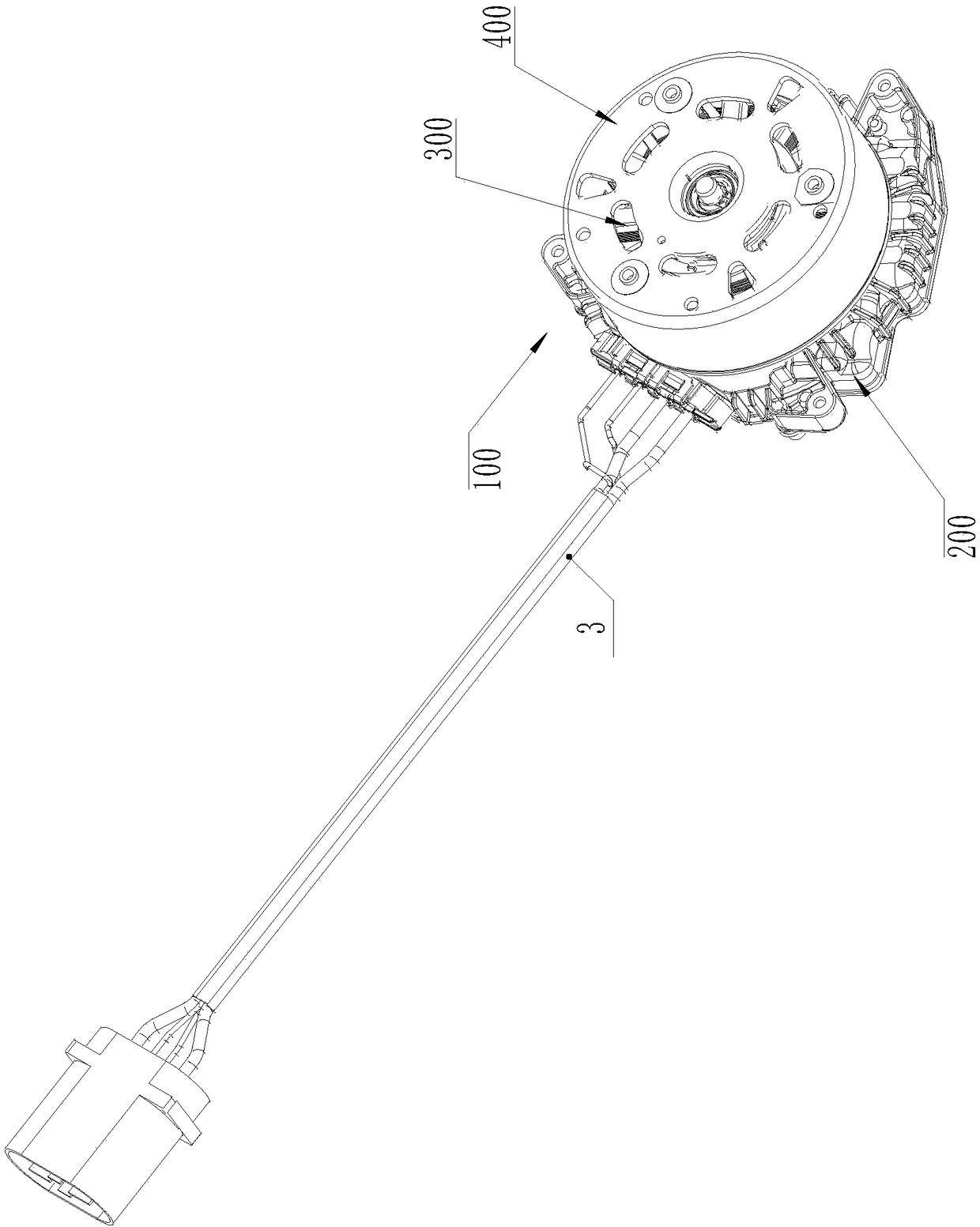
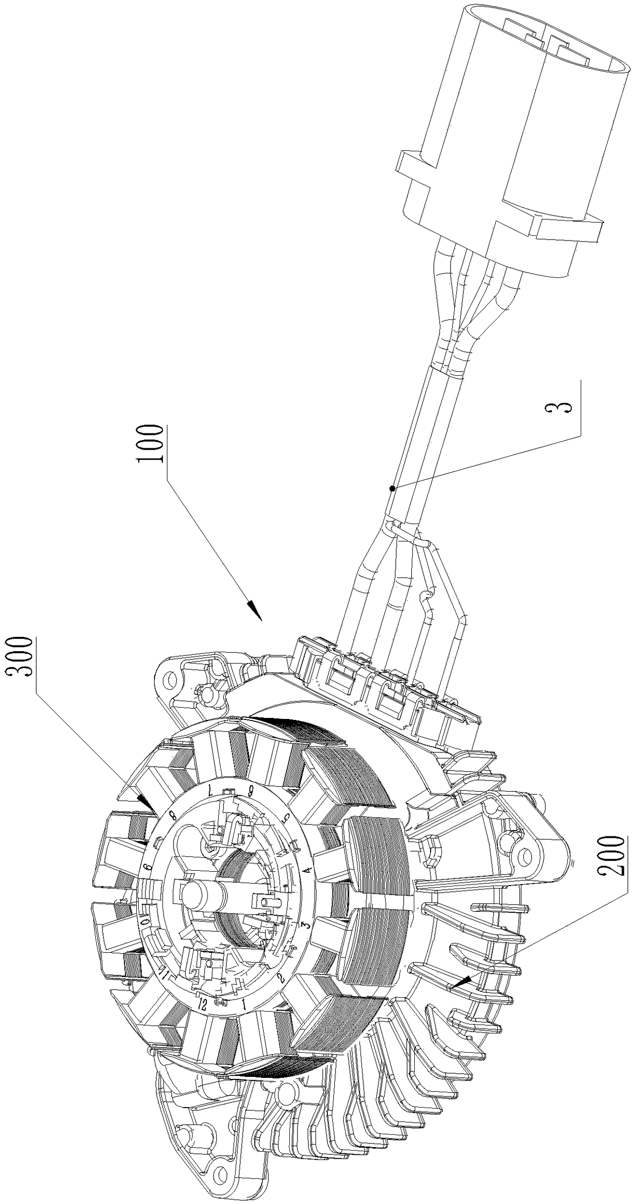
[0047] Such as Figure 1 to Figure 13 As shown, a driving motor 100 for an automobile cooling fan includes a controller assembly 200 , a stator winding 300 and an outer rotor assembly 400 .

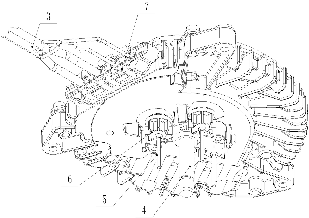
[0048] The controller assembly 200 includes a housing composed of a heat sink 1 and a rear end cover 2, a conductive support 11 and a PCBA board 8 are arranged inside the housing, a central shaft 4 is provided on the front of the heat sink 1, and the stator winding 300 is fixed on the front of the heat sink 1, the central shaft 4 is located at the center of the positioning winding, the outer rotor assembly 400 is rotatably mounted on the central shaft 4, and the heat sink 1 is provided with a capacitor installation area 102, an inductor installation Area 104, conductive bracket installation area 106, wire harness joint area 105 and heat conduction platform 101, described conductive bracket...


PUM


Abstract

The invention discloses a driving motor for an automobile cooling fan, comprising a controller assembly, a stator winding and an outer rotor assembly, wherein the controller assembly comprises a heatsink, a rear end cover, a conductive bracket and a PCBA board; three through holes are disposed in the heat sink; three mounting holes are disposed in the conductive bracket; positioning embedding grooves are disposed in the back of the conductive bracket; a conductive link is inserted into each mounting hole; the front end of each conductive link is electrically connected to a corresponding coilof the stator winding; a tail section of each conductive link is bent and then embedded into the corresponding positioning embedding groove; the tail end of each conductive link stretches out of the corresponding positioning embedding groove after being bent; the heat sink and the conductive bracket are provided with positioning support structures for positioning and supporting the PCBA board, andinductors, capacitors, conductive links and wire harness conductive pins are all welded and fixed to corresponding conductive holes in the PCBA board. According to the driving motor for the automobile cooling fan, the stator winding and the PCBA board are better electrically connected, conductive pieces are omitted, the welding operation is simpler, and the conductive efficiency is improved.

Description

technical field [0001] The invention relates to a driving motor, which is used to drive a cooling fan of an automobile. Background technique [0002] Motors are commonly used power devices and are used in various industries. At present, brushless motors can be controlled by PCBA boards. The structure of the brushless motor mainly includes a controller assembly, a stator assembly, and a rotor assembly, wherein the controller assembly includes a shell composed of a heat sink and a rear end cover, and a conductive support and a PCBA board are arranged in the shell, and the heat sink There is a central axis on the front of the heat sink, and the heat sink is provided with a capacitor installation area, an inductance installation area, a conductive bracket installation area, and a harness joint area. The conductive bracket is installed in the conductive bracket installation area, and the capacitor and inductor are installed in the corresponding area. , the PCBA board is located ...

Claims


Application Information

Patent Timeline
IPC IPC(8): H02K11/33H02K3/50
CPCH02K3/50H02K11/33Y02T10/64
Inventor 戚纯波徐迎宾陈志强
Owner JIANGSU LANGXIN ELECTRIC
Why Eureka
Try Eureka