A multi-output linear sweep frequency source for an interferometric radar and a control method thereof

A multi-output, interferometric radar technology, used in automatic power control, radio wave measurement systems, electrical components, etc., can solve problems such as poor linearity, complex design algorithms, and insufficient bandwidth, and achieve excellent signal integrity. , excellent high frequency characteristics, strong compatibility effect

Active Publication Date: 2018-12-11
NANHAI RES STATION OF INST OF ACOUSTICS CHINESE ACADEMY OF SCI
View PDF4 Cites 6 Cited by
  • Summary
  • Abstract
  • Description
  • Claims
  • Application Information

AI Technical Summary

Problems solved by technology

This kind of scheme is used in many systems. Its advantages are high integration and easy implementation with digital methods, but its disadvantages are that the design algorithm is more complicated, the power consumption is larger, and it is difficult to achieve SAR in terms of linearity index and bandwidth. Accuracy required by the system
[0006] Earlier FMCW radar systems, including many 24G automotive radars, generally use VCO directly, and the triangular wave signal generated externally controls its direct oscillation to generate the corresponding radar signal source, but this method is easily affected by external factors and is not very stable. , the linearity is generally about + / -5%
It is difficult to meet the needs of the current high-precision SAR radar system
Existing linear frequency sweeping sources have disadvantages such as poor linearity, insufficient frequency band, insufficient standing wave ratio, large power consumption, and single signal output frequency band.
[0007] The above-mentioned frequency scanning sources have their own advantages and disadvantages, and it is difficult to fully meet the requirements of high-precision, high-resolution small-scale interferometric radar systems, and most of them are single-channel output, and the compatibility is not strong

Method used


Image

  • A multi-output linear sweep frequency source for an interferometric radar and a control method thereof
  • A multi-output linear sweep frequency source for an interferometric radar and a control method thereof
  • A multi-output linear sweep frequency source for an interferometric radar and a control method thereof

Examples


Embodiment 1

[0066] Example 1: Three-way output linear frequency sweep source

[0067] The invention is designed to make up for the shortcomings of the linear sweep frequency source, such as poor linearity, insufficient frequency band, insufficient standing wave ratio, large power consumption, and single signal output frequency band. A miniaturized, high-indicator three-output linear sweep signal source is designed, which meets the requirements of the existing SAR radar system and can be applied to a variety of band miniaturized SAR radar systems.

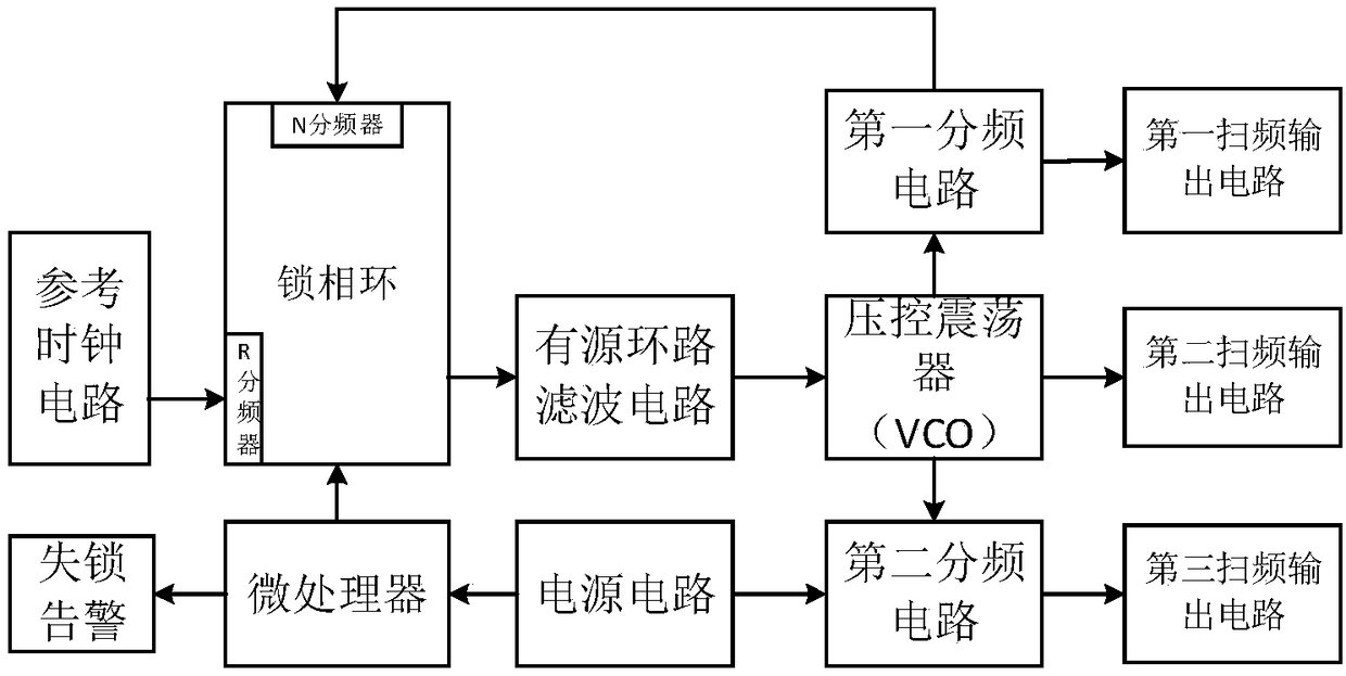
[0068] Such as figure 1 As shown, the present invention provides a three-way output linear sweep source for interference radar, including: power supply circuit, microprocessor, reference clock circuit, phase-locked loop circuit, active loop filter circuit, voltage-controlled oscillation device, a first frequency sweep output circuit, a second frequency sweep output circuit, a third frequency sweep output circuit and a high frequency mixed volt...

Embodiment 2

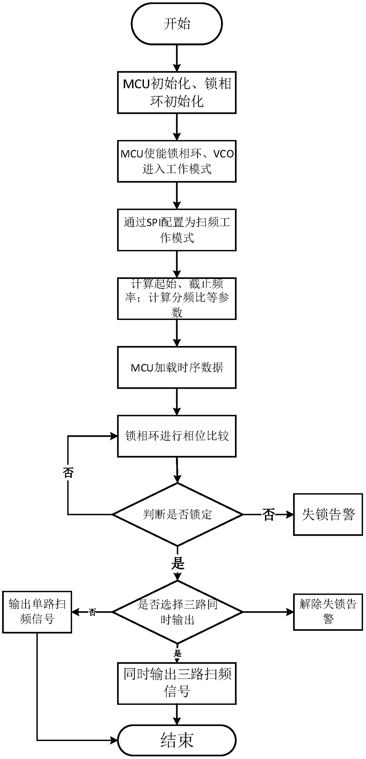
[0084] Such as image 3 As shown, Embodiment 2 of the present invention provides a control method for a three-way output linear frequency sweep source, and the method includes:

[0085] Step S1) Connect the power supply circuit, the linear frequency sweep source is initialized and starts to run, the schematic diagram of the power supply is as follows Figure 4 shown;

[0086] This step specifically includes:

[0087] Step S1-1) output voltage V of the first power supply voltage stabilizing circuit OUT1 The calculation method formula is as follows:

[0088] R2=R1 / {(V OUT1 / 0.81)-1}

[0089] L=V OUT1 ×(V IN -V OUT1 ) / V IN ×ΔI L × f sw

[0090] Among them, R2 and R1 are the feedback resistors, L is the output power inductor, V OUT1 is the output voltage, V in is the input voltage, ΔI L is the ripple current, f sw is the switching frequency.

[0091] Step S1-2) The formula for calculating the output voltage of the second power supply voltage stabilizing circuit is...


PUM


Abstract

The invention discloses a multi-output linear sweep frequency source for an interferometric radar. The linear sweep frequency source comprises a PCB circuit board, and a microprocessor, a reference clock circuit, a phase locked loop circuit, an active loop filter circuit, a voltage controlled oscillator, a frequency dividing circuit and a sweep frequency output circuit arranged on the PCB circuitboard. The microprocessor is used for controlling the working mode of the frequency sweeping source, and the phase locked loop circuit is logically controlled to output the frequency sweeping frequency. The reference clock circuit is used for generating an external reference frequency and supplying the reference frequency to the phase locked loop circuit. The phase-locked loop circuit is used forcarrying out logic calculation and frequency synthesis. The active loop filter circuit is used for filtering and attenuating the high-frequency noise in the output voltage of the phase-locked loop, and then outputting the high-frequency noise to the voltage-controlled oscillator. The voltage controlled oscillator is used for generating an original frequency signal according to the input voltage oscillation and outputting the original frequency signal to a frequency dividing circuit and a frequency sweeping output circuit. The frequency dividing circuit is used for dividing and filtering the original frequency signal according to the frequency dividing parameters.

Description

technical field [0001] The invention relates to the technical field of multi-channel output frequency synthesis sources, in particular to a multi-channel output linear frequency sweep source for interference radar and a control method thereof. Background technique [0002] With the increasing popularity of light and miniaturized platforms such as unmanned aerial vehicles and small bombs, radars have high-resolution imaging capabilities and are competent to work in harsh weather environments. Therefore, radar imaging technology is more and more popular; many scholars pay attention to the micro SAR system with low power consumption, low cost and light weight. The miniaturization and high-resolution characteristics of interferometric radar put forward higher technical requirements for related technologies, so designing a high-performance linear sweep signal source is very important to improve radar performance. [0003] The role of the linear frequency sweep source in the SAR ...

Claims


Application Information

Patent Timeline
Patent Type & Authority Applications(China)
IPC IPC(8): H03L7/18G01S7/02
CPCG01S7/023H03L7/18
Inventor 李松斌袁名勇
Owner NANHAI RES STATION OF INST OF ACOUSTICS CHINESE ACADEMY OF SCI
Why Eureka
Try Eureka