
Calibration method of three-dimensional electronic compass

An electronic compass and calibration method technology, applied in the direction of measuring devices, instruments, etc., can solve problems such as difficulty in meeting field operations, and achieve the effect of eliminating soft and hard magnetic interference, flexible calibration process, and good effect.

Active Publication Date: 2018-12-21
FUZHOU UNIV
View PDF7 Cites 5 Cited by
  • Summary
  • Abstract
  • Description
  • Claims
  • Application Information

AI Technical Summary

Problems solved by technology

Difficult to meet the needs of field operations

Method used


Image

  • Calibration method of three-dimensional electronic compass
  • Calibration method of three-dimensional electronic compass
  • Calibration method of three-dimensional electronic compass

Examples


Embodiment Construction

[0061] The technical solution of the present invention will be specifically described below in conjunction with the accompanying drawings.

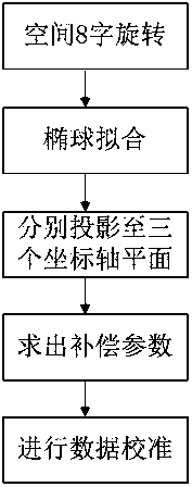
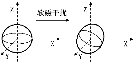
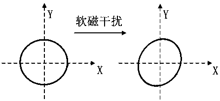
[0062]The invention provides a method for calibrating a three-dimensional electronic compass. The electronic compass is moved in a figure-of-eight motion in space, and the data read by the three axes of the magnetic sensor are collected; then the collected data are fitted with an ellipsoid to obtain The spherical equation and the coordinates of the center of the sphere; then project the fitted ellipsoid equation onto the three coordinate axis planes respectively, and obtain the parameters of the ellipse on the three planes: α, b, and major axis rotation angle; finally, according to the obtained Parameter pairs for data calibration. The specific implementation steps of this method are as follows:

[0063] Step S1: Make the electronic compass move in figures of eight in space, so that the electronic compass collects data corresponding to e...


PUM


Abstract

The invention relates to a calibration method of a three-dimensional electronic compass, comprising the following steps: performing 8-shaped moving in the space on the electronic compass, collecting data read out by three axes of a magnetic sensor; then performing ellipsoidal fitting on the collected data to obtain an ellipsoidal equation and a spherical center coordinate; respectively projectingthe obtained ellipsoidal equation to three coordinate axis planes, and respectively solving parameters of the ellipses on the three planes: a, b, a long axis rotational angle; and finally performing calibrating on the newly obtained data according to the obtained parameters. According to the calibration method of the three-dimensional electronic compass, the electronic compass is more flexible inthe calibration process, higher in accuracy, and meets the requirement of field activities.

Description

technical field [0001] The invention relates to a method for calibrating a three-dimensional electronic compass. Background technique [0002] In recent years, electronic compasses have been widely used in navigation, human body posture measurement and other scenarios. Since the GPS signal is very weak in places such as forests and dense buildings, an electronic compass is usually needed to assist in positioning. [0003] The working principle of the electronic compass is to measure the component strength of the geomagnetism in a certain direction through a magnetic sensor, determine the angle between the sensor and the geomagnetism, and then determine the heading. However, the earth's magnetic field is a weak magnetic field, and the hard magnetic interference and soft magnetic interference brought by the magnetic materials around the electronic compass will cause the measured value of the magnetic sensor to deviate from the true value. In addition, due to the process prob...

Claims


Application Information

Patent Timeline
Patent Type & Authority Applications(China)
IPC IPC(8): G01C25/00
CPCG01C25/00
Inventor 魏榕山曾濯渠杨培祥
Owner FUZHOU UNIV
Learn More