Track detector

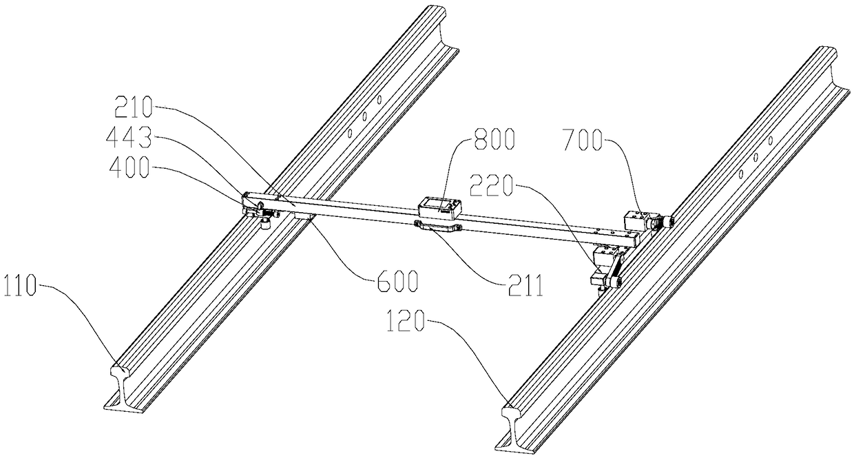
A detector and track technology, applied in the field of track detectors, can solve the problems of low gauge measurement efficiency and low measurement accuracy, and achieve the effect of avoiding inaccurate gauge measurement and improving the accuracy of gauge measurement.

Active Publication Date: 2019-01-29
重庆恒悍机电设备有限公司
View PDF4 Cites 9 Cited by
  • Summary
  • Abstract
  • Description
  • Claims
  • Application Information

AI Technical Summary

Problems solved by technology

[0004] Aiming at the defects of low gauge measurement efficiency and low measurement accuracy in the prior art, the present invention provides a track detector, which can not only improve the gauge measurement accuracy, but also improve the measurement efficiency

Method used


Image

  • Track detector
  • Track detector
  • Track detector

Examples


Embodiment Construction

[0044] Here, it should be noted that the functions and methods involved in the present invention are merely conventional adaptive applications of the prior art. Therefore, the improvement of the present invention to the prior art lies in the connection relationship between the hardware, rather than the functions and methods themselves. Improve. The description of the functions and methods in the present invention is to better illustrate the present invention so as to better understand the present invention.

[0045]Embodiments of the technical solutions of the present invention will be described in detail below in conjunction with the accompanying drawings. The following examples are only used to illustrate the technical solutions of the present invention more clearly, and therefore are only examples, rather than limiting the protection scope of the present invention.

[0046] It should be noted that, unless otherwise specified, the technical terms or scientific terms used i...


PUM


Abstract

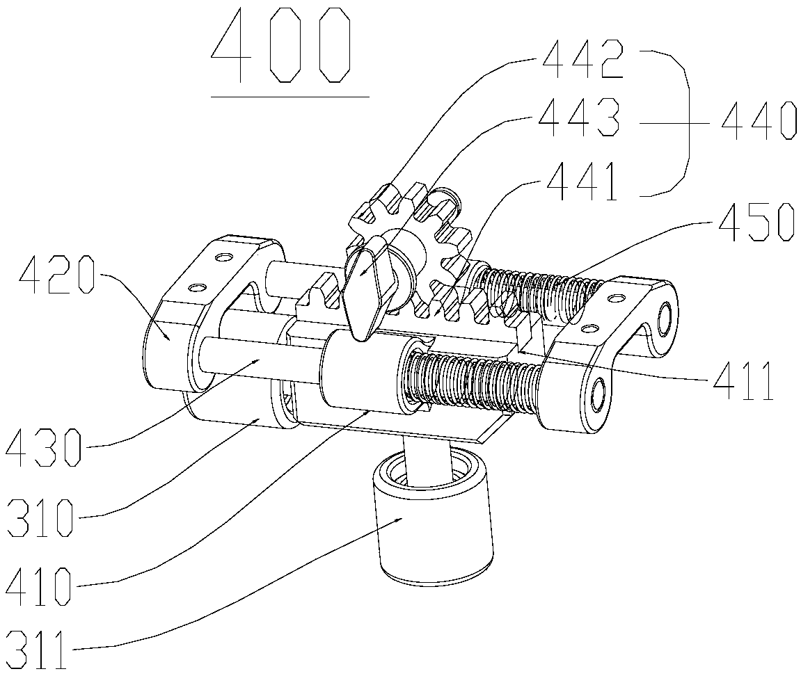
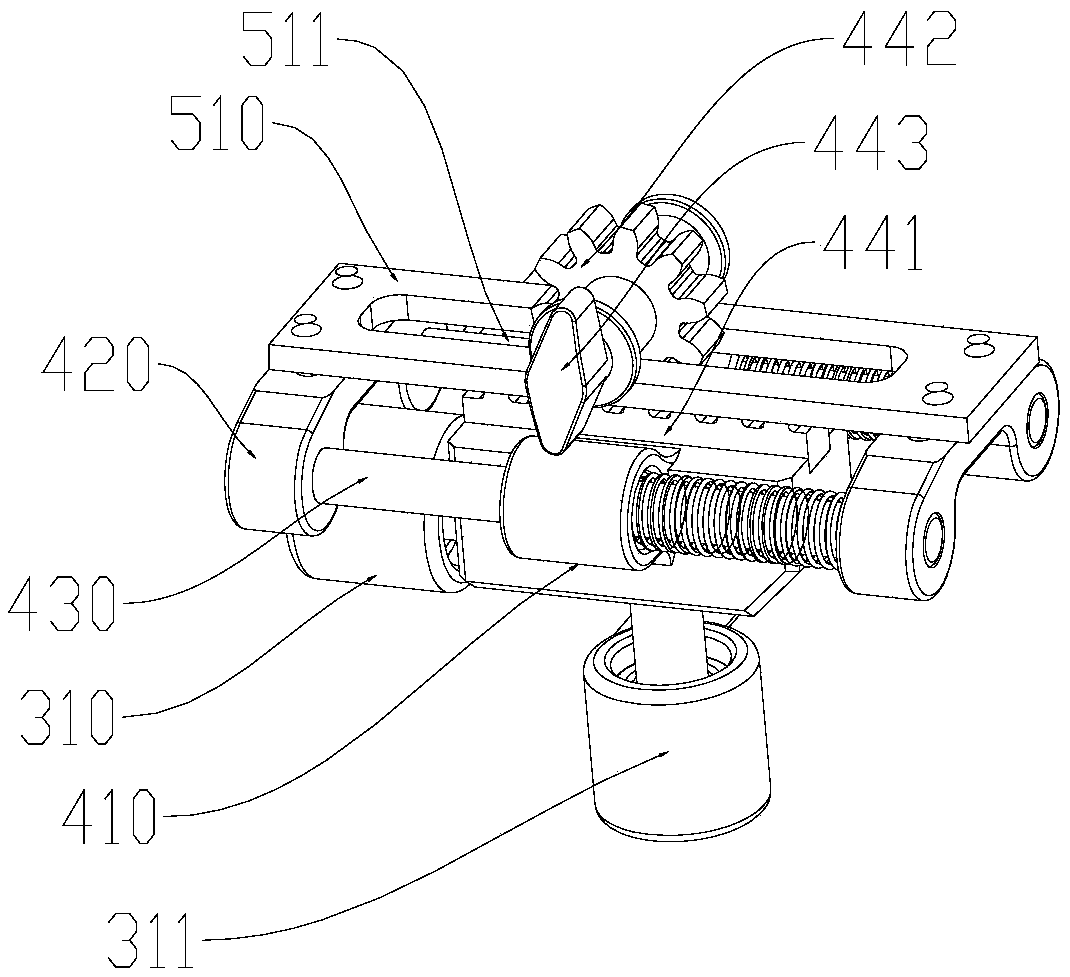
The invention provides a track detector. The track detector is used for detecting corresponding data of a track, comprises a main beam mounted on the track and a traveling wheel assembly which slidesalong the track, and further comprises a secondary beam, at least one traveling wheel adjusting assembly, a distance measuring assembly and a driving assembly. The secondary beam is parallel to the track and connected with the bottom of one end of the main beam; the traveling wheel adjusting assemblies are disposed at the bottom of the end, away from the secondary beam, of the main beam; the distance measuring assembly is disposed below the main beam and adjacent to the traveling wheel adjusting assemblies, and a signal transmitting point of the distance measuring assembly faces the travelingwheel adjusting assemblies, the driving assembly is disposed on the secondary beam for driving the traveling wheel assemblies to move. The traveling wheel assembly comprises left traveling wheel setsand right traveling wheel sets, the right traveling wheel sets are separately disposed at both ends of the secondary beam and are driven by the driving assembly to slide along a right track; the lefttravelling wheel sets are disposed on the travel wheel adjusting assemblies and slide along a left track; and the travelling wheel adjusting assemblies are used for enabling the left travelling wheelsets to slide by tightly attaching to the left track. The travelling wheel sets are attached to the track by the travelling wheel adjusting assemblies to improve the gauge measurement accuracy.

Description

technical field [0001] The invention relates to the field of railway track detection, in particular to a track detection instrument. Background technique [0002] In the stage of railway construction, after the laying of the railway track is completed, it is necessary to detect the absolute position and relative position of the track, and adjust the position that does not meet the design requirements to ensure the safe and comfortable operation of the train. During the long-term operation of the railway, the track will change due to long-term use wear, subgrade settlement, loose fasteners and other reasons, resulting in changes in the absolute and relative state of the local position of the track. These changes will seriously affect the safety and comfort of train operation, and these improvements must be detected and adjusted, and the gauge is one of the important detection objects. [0003] The gauge refers to the distance between the gauge points at 16mm below the 120 wo...

Claims


Application Information

Patent Timeline
Patent Type & Authority Applications(China)
IPC IPC(8): E01B35/04
CPCE01B35/04E01B2203/16
Inventor 缪祎杰陈德国缪晓渝熊焕国周露李国瑞罗川萍张震远张文彬唐玉平沈龙乐吴建滨赖文华何继平王乾宇
Owner 重庆恒悍机电设备有限公司
Why Eureka
Try Eureka