
Image forming apparatus

An image, closed position technology, used in printing devices, electrographics, optics, etc., to solve problems such as paper jams, different positions of recording sheet guides, paper jams, etc.

Active Publication Date: 2019-02-12
KYOCERA DOCUMENT SOLUTIONS INC
View PDF12 Cites 0 Cited by
  • Summary
  • Abstract
  • Description
  • Claims
  • Application Information

AI Technical Summary

Problems solved by technology

[0004] However, in the image forming apparatus described above, no consideration has been given to positioning the exterior door on the cabinet with good accuracy.
Therefore, there is a problem that the position of the recording sheet guide relative to the case differs each time the exterior door is opened and closed.
When the position of the recording sheet guide deviates greatly from the proper position, the recording sheet cannot be conveyed reliably, which may cause paper jams (paper jams)

Method used


Image

  • Image forming apparatus
  • Image forming apparatus
  • Image forming apparatus

Examples


Embodiment Construction

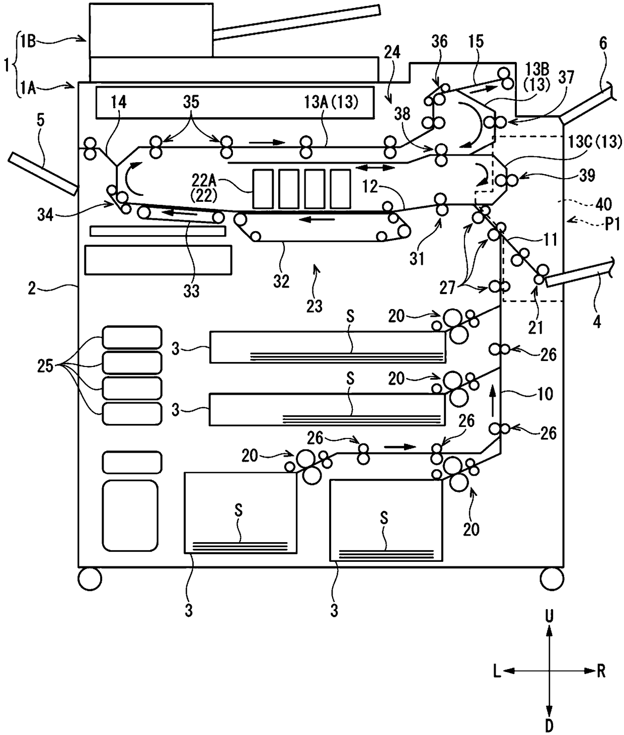
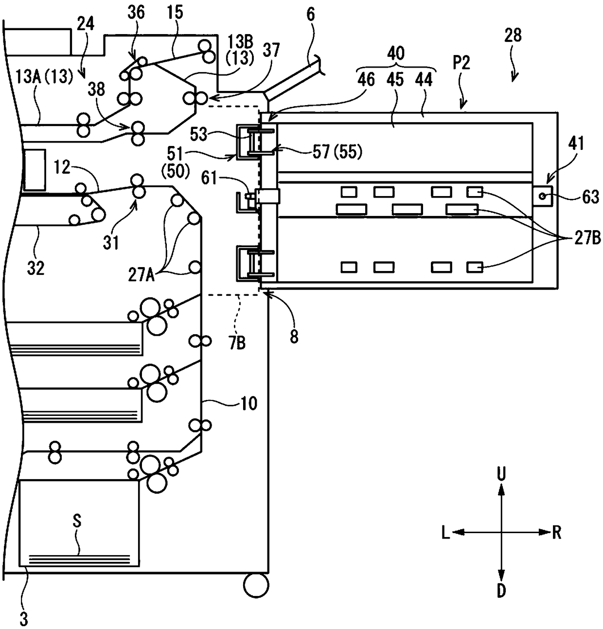
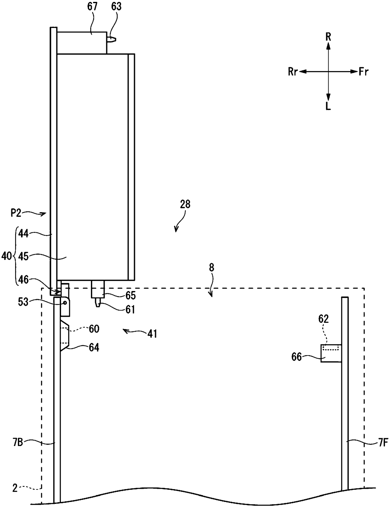
[0016] Embodiments of the present invention will be described below with reference to the drawings. In addition, to figure 1 The front side of the paper is the front, "Fr" in each figure means "front", "Rr" means "rear", "L" means "left", "R" means "right", "U" means " "Up", "D" means "Down". In addition, in the following description, the term "conveying direction" refers to the conveying direction of the sheet S, and terms such as "upstream" and "downstream" and the like refer to "upstream" and "downstream" of the conveying direction and Similar concepts to these. These words indicating directions are used for convenience of description and do not limit the technical scope of the present invention.

[0017] refer to figure 1 The overall configuration of image forming apparatus 1 according to this embodiment will be described. figure 1 is a cross-sectional view schematically showing the internal structure of the image forming apparatus 1 .

[0018] The image forming appa...


PUM


Abstract

The invention provides an image forming apparatus. An image forming apparatus includes a pair of support frames, an opening and closing door and a positioning structure. The pair of support frames arearranged oppositely at both sides of an opening. The opening and closing door is supported by one of the pair of support frames via a turning shaft and turns around the turning shaft between a closing position where the opening and closing door closes the opening and an opening position where the opening and closing door opens the opening. The positioning structure positions the opening and closing door to the pair of support frames by engaging a convex part or a concave part provided in the pair of support frames with a concave part or a convex part provided in the opening and closing door in a state where the opening and closing door is turned to the closing position. According to the invention, the opening and closing door can be positioned to the pair of support frames with good precision.

Description

technical field [0001] The present invention relates to an image forming apparatus. Background technique [0002] The image forming apparatus has an opening and closing door that opens the side of the apparatus main body in order to remove sheets clogging the conveyance path. [0003] For example, an image forming apparatus includes: an exterior door rotatably supported around a rotation shaft extending in an up-down direction along a side surface of a housing; and a swing guide rotatable about a rotation shaft extending in a horizontal direction. It is supported on the inner side of the exterior door to open the sheet conveying path. A recording sheet guide constituting a sheet conveyance path for conveying recording sheets is provided inside the exterior door. [0004] However, in the image forming apparatus described above, no consideration has been given to positioning the exterior door on the cabinet with high precision. Therefore, there is a problem that the positio...

Claims


Application Information

Patent Timeline
IPC IPC(8): G03G21/16
CPCG03G21/1695B41J29/13B41J29/02B41J2/01
Inventor 大西正人
Owner KYOCERA DOCUMENT SOLUTIONS INC
Learn More