Cup lifting device and reaction cup loading system

A technology for loading systems and cuvettes, applied to the analysis of materials, instruments, etc., can solve problems such as high failure rate, high cost, and numerous modules

Pending Publication Date: 2019-02-22
SYSCAN MEDICAL TECH SUZHOU
View PDF1 Cites 2 Cited by
  • Summary
  • Abstract
  • Description
  • Claims
  • Application Information

AI Technical Summary

Problems solved by technology

This system uses multiple pneumatic components, chain transmission, etc., so the system has complex pro

Method used


Image

  • Cup lifting device and reaction cup loading system
  • Cup lifting device and reaction cup loading system
  • Cup lifting device and reaction cup loading system

Examples


Embodiment Construction

[0020] The application will be further described below in conjunction with the accompanying drawings and specific embodiments, so that those skilled in the art can better understand the application and implement it, but the examples given are not intended to limit the application.

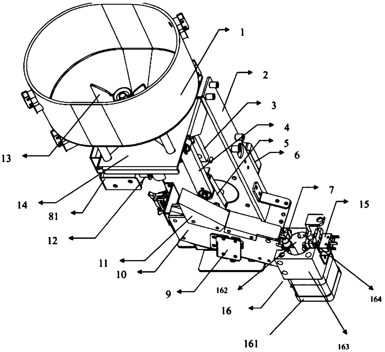
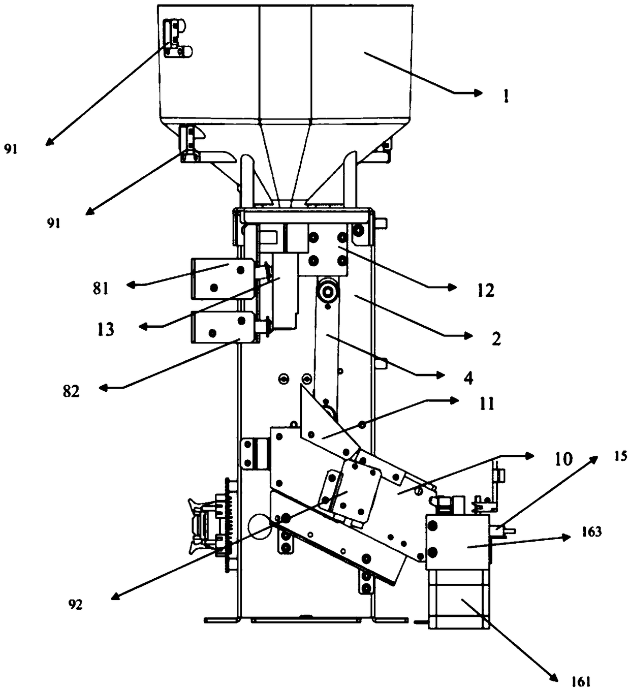
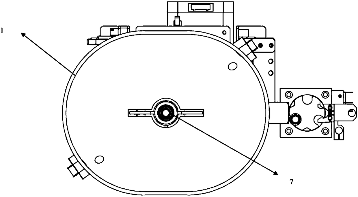
[0021] As shown in the figure, it is the cuvette loading system of the present application. The loading system includes a cup raising device 16, the cup raising device 16 includes a rotating member 162 that can rotate around its own axis, a drive motor 161 for driving the rotating member 162, and the rotating member 162 penetrates up and down A plurality of cuvette installation slots 164 for placing cuvettes are provided, and the cup raising device 16 also includes a support member, and the support member has a slope located at the lower side of the cuvette installation slots, so The distance between the cuvette installation groove and the inclined plane changes with the rotation of the rotating me...


PUM


Abstract

The invention provides a cup lifting device and a reaction cup loading system. The cup lifting device comprises a rotary member capable of rotating about the own axis and a drive motor for driving therotation of the rotary member, and further comprises a supporting member. The rotary member is provided with a plurality of reaction cup mounting grooves for placing reaction cups in an up-down penetrating mode. The supporting member is provided with an inclined surface located on the lower side of the reaction cup mounting grooves, and the distance between the reaction cup mounting grooves and the inclined surface is varied as the rotary member rotates. The drive motor drives the rotation of the rotary member to enable the reaction cups to be lifted by the inclined surface, so that a grippercan conveniently take the reaction cups away.

Description

technical field [0001] The present application relates to a cup raising device and a reaction cup loading system. Background technique [0002] As the automation degree of the analysis device and the requirements for the test speed are getting higher and higher, an automatic loading system is required to provide the analyzer with the cuvettes required for the test. A cuvette system capable of automatically providing an analysis device with testing requirements has been documented in public documents, such as US2002106305A1. This patent provides a loading device for automatically transporting cuvettes, which includes a storage bin for storing cuvettes, a transmission chain with hooks, and a cuvette guiding mechanism. The storage compartment stores a certain number of cuvettes. The transmission chain with hooks is driven by the motor, and the chain moves from bottom to top. The hooks on the chain move up one by one with the cuvettes in the storage compartment. When they reach...

Claims


Application Information

Patent Timeline
IPC IPC(8): G01N35/04G01N35/02
CPCG01N35/026G01N35/04G01N2035/0444
Inventor 吴武彬杨科李帆岳文杰
Owner SYSCAN MEDICAL TECH SUZHOU
Why Eureka
Try Eureka