Valve for controlling a fluid
What is Al technical title?
Al technical title is built by PatSnap Al team. It summarizes the technical point description of the patent document.
A technology for controlling fluids and shells, which is applied in the direction of lift valves, multi-way valves, valve devices, etc., and can solve problems such as insulation layer material weakening, short circuit, etc., and achieve the effect of long service life
Active Publication Date: 2019-03-15
MSG MECHATRONIC SYST
View PDF10 Cites 0 Cited by
Summary
Abstract
Description
Claims
Application Information
AI Technical Summary
This helps you quickly interpret patents by identifying the three key elements:
Problems solved by technology
Method used
Benefits of technology
Problems solved by technology
Direct contact between the fluid and the coil can lead to a weakening of the material of the insulation surrounding the wires of the coil and thus to short circuits, especially if the fluid is corrosive or aggressive
Method used
Image
Click on the blue label to locate the original text in one second.
Reading with bidirectional positioning of images and text.
Examples
Embodiment Construction
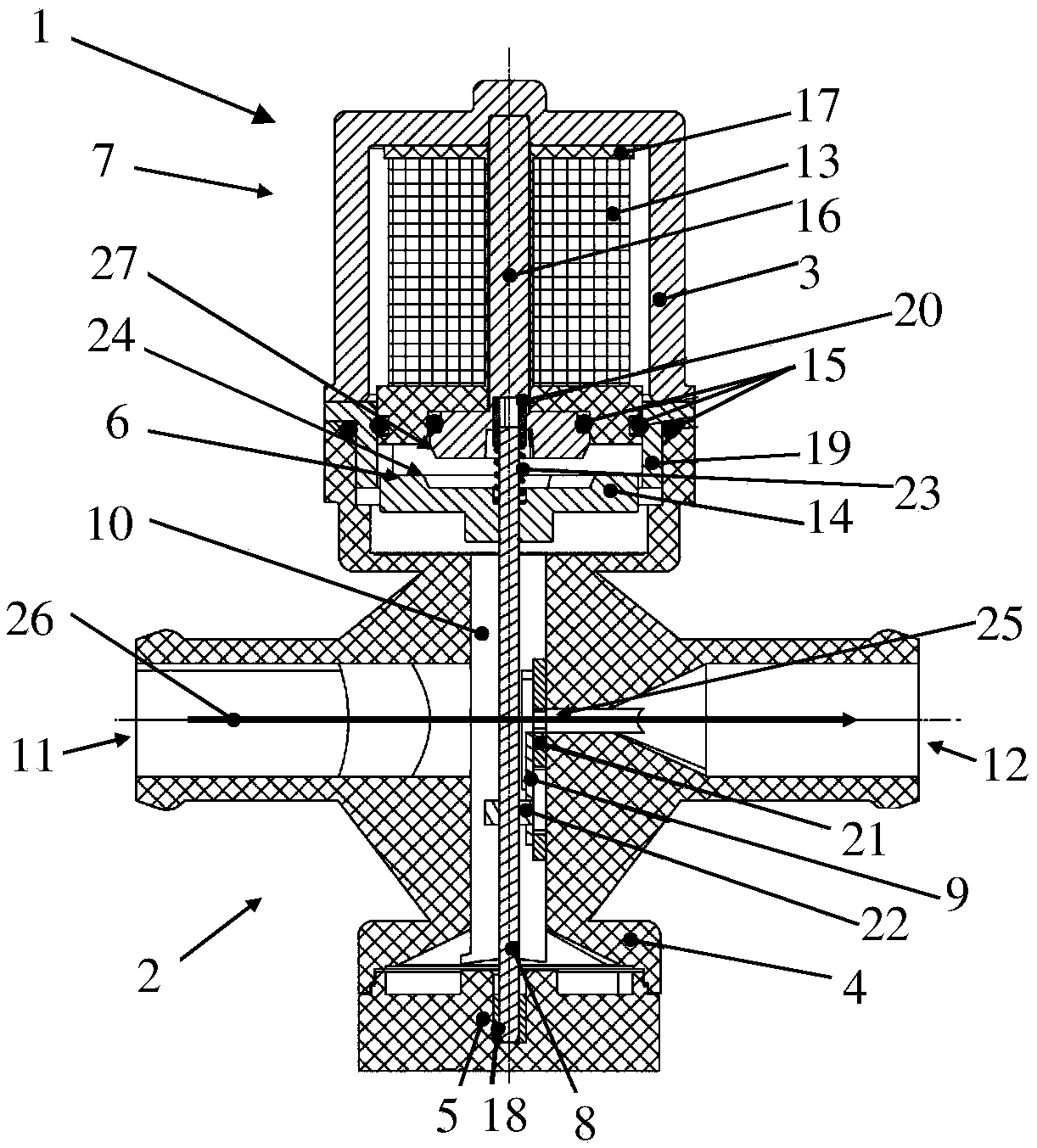
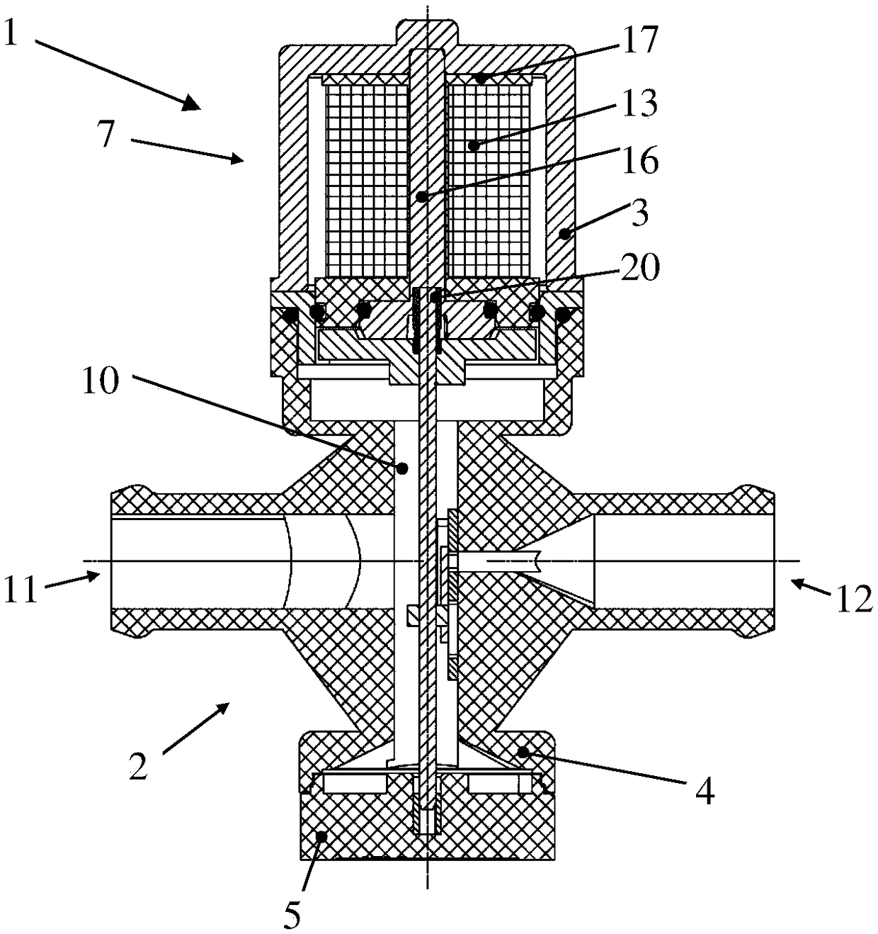
[0027] figure 1 and 2 A first embodiment of a valve 1 for controlling fluids according to the invention is shown in a side sectional view. The valve 1 comprises a housing 2 and an actuation unit 7 . The actuating unit 7 comprises a coil housing 3 connected to the housing 2 via a flange 19 , a coil 13 arranged in the coil housing 3 , a coil body 17 , an iron core 16 , a sliding sleeve 20 and an armature 14 . The coil 13 is surrounded by a coil body 17 and can be connected to a power source by a cable not shown. The coil 13 surrounds a core 16 which is connected to the core housing 3 . The armature 14 is disk-shaped and has a circular projection 6 , wherein a cone is formed on the circular projection 6 at its jacket inner surface 24 .
[0028] The core 16 has a cone 27 at the end facing the armature 14 .
[0029] Arranged between housing 2 , flange 19 and core 16 are O-rings 15 which statically seal coil 13 from cavity 10 formed in housing 2 . This offers the advantage tha...
PUM
Abstract
A valve (1, 28, 36, 51), comprising a housing (2, 38, 52) with an inlet (11, 40) and an outlet (12, 29, 41), a closure (9, 30, 47, 53), which is displaceable between a first position and a second position, wherein in the first position, a flow path (26, 34, 35, 50, 57) from the inlet (11, 40) to the outlet (12, 29, 41) is formed or interrupted, and wherein the flow path (26, 34, 35, 50, 57) is interrupted or formed in the second position, and an actuation unit (7) having a coil (13) and an armature (14, 37). The armature displaces the closure between the two positions subject to a current applied to the coil (13), wherein the armature (14, 37) has a cone, wherein a force on the armature (14, 37) is modifiable via an ascent of the cone.
Description
technical field [0001] The invention relates to a valve for controlling a fluid, which has the features of the preamble of claim 1 . Background technique [0002] Utility model DE 20 2010 004 556 U1 discloses a valve for controlling fluids, comprising a housing with a tubular cavity to which three connecting pieces are connected. Inside the tubular cavity there is a cylindrical closure with several grooves and displaceable between a first position and a second position. In the first position of the closure there is a flow path between two of the three connections and in the second position between the other two of the three connections, while in each case Both of them prevent fluid from flowing to the remaining third connector. Furthermore, the valve has an actuation unit comprising a stationary coil with a housing and a movable armature. The armature is flat, is coupled to the closure, and is arranged on the surface of the coil within the cavity, the armature being surro...
Claims
Application Information
Patent Timeline
Application Date:The date an application was filed.
Publication Date:The date a patent or application was officially published.
First Publication Date:The earliest publication date of a patent with the same application number.
Issue Date:Publication date of the patent grant document.
PCT Entry Date:The Entry date of PCT National Phase.
Estimated Expiry Date:The statutory expiry date of a patent right according to the Patent Law, and it is the longest term of protection that the patent right can achieve without the termination of the patent right due to other reasons(Term extension factor has been taken into account ).
Invalid Date:Actual expiry date is based on effective date or publication date of legal transaction data of invalid patent.