
High-power factor LED drive power source low-frequency ripple wave inhibition method

A technology of LED driving and high power factor, applied in the field of LED driving power supply, can solve the problems of large output current and low frequency ripple, limited application, stroboscopic and other problems, and achieve the effect of high power factor and low frequency ripple suppression.

Active Publication Date: 2019-03-19
FUZHOU UNIV
View PDF8 Cites 3 Cited by
  • Summary
  • Abstract
  • Description
  • Claims
  • Application Information

AI Technical Summary

Problems solved by technology

The two-stage circuit topology usually adopts the circuit structure of Boost-PFC converter and DC / DC converter. The front-stage Boost-PFC converter realizes the power factor correction function, and the rear-stage DC / DC converter realizes the constant current control of the LED lamp. However, the LED drive power supply using a two-stage power conversion circuit, the output energy has undergone two-stage power conversion, low efficiency, high cost, and complex circuit structure, which limits its application in LED drive power supplies
Single-stage circuit topology is widely used in low-power applications due to its simple structure, low cost, high power factor, and high efficiency. However, due to the imbalance between instantaneous input power and constant output power, the output current There is a large low-frequency ripple, which causes stroboscopic problems when the LED is working

Method used


Image

  • High-power factor LED drive power source low-frequency ripple wave inhibition method
  • High-power factor LED drive power source low-frequency ripple wave inhibition method
  • High-power factor LED drive power source low-frequency ripple wave inhibition method

Examples


Embodiment Construction

[0024] The present invention will be further described below in conjunction with the accompanying drawings and embodiments.

[0025] It should be pointed out that the following detailed description is exemplary and is intended to provide further explanation to the present application. Unless defined otherwise, all technical and scientific terms used herein have the same meaning as commonly understood by one of ordinary skill in the art to which this application belongs.

[0026] It should be noted that the terminology used here is only for describing specific implementations, and is not intended to limit the exemplary implementations according to the present application. As used herein, unless the context clearly dictates otherwise, the singular is intended to include the plural, and it should also be understood that when the terms "comprising" and / or "comprising" are used in this specification, they mean There are features, steps, operations, means, components and / or combina...


PUM


Abstract

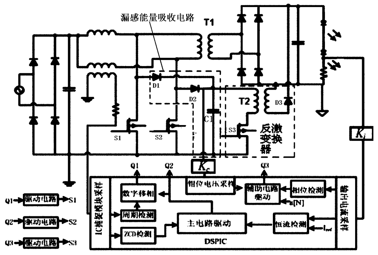
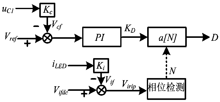
The invention relates to a high-power factor LED drive power source low-frequency ripple wave inhibition method. An AC power supply, a rectifier circuit, a single-stage power factor correction circuit, an LED load and a ripple suppression circuit are provided. The AC power supply is connected with the input end of the rectifier circuit, the positive and negative output ends of the rectifier circuit are connected with positive and negative input ends of the single-stage power factor correction circuit, the output of the single-stage power factor correction circuit is connected with output of the ripple suppression circuit in parallel to supply power to the LED load. The high-power factor LED drive power source low-frequency ripple wave inhibition method can inhibit low-frequency ripple waveof the LED lamp current and effectively utilizes the leakage inductance energy.

Description

technical field [0001] The invention relates to the field of LED driving power supply, in particular to a method for suppressing low-frequency ripple of a high power factor LED driving power supply. Background technique [0002] With its many advantages such as energy saving, environmental protection, high efficiency and long life, LED has become a new generation of green lighting source. With the maturity of LED lighting technology, it will be widely used in various fields. In the case of AC power supply, in order to meet the harmonic requirements of IEC61000-3-2, LED drive power supply needs to perform power factor correction. [0003] LED drive power supply with power factor correction function can be divided into single-stage circuit topology and two-stage circuit topology according to its topology. The two-stage circuit topology usually adopts the circuit structure of Boost-PFC converter and DC / DC converter. The front-stage Boost-PFC converter realizes the power facto...

Claims


Application Information

Patent Timeline
Patent Type & Authority Applications(China)
IPC IPC(8): H05B33/08H05B44/00
CPCH05B45/00
Inventor 林国庆苏锦文林梅珍
Owner FUZHOU UNIV
Learn More