
Method for internally placing Fabry-Perot cavity pressure fiber sensor probe

A technology of optical fiber sensor and pressure sensor, which is applied in the field of transformers, can solve problems such as the inability to determine the state of the coil, achieve the effect of simple and reliable internal placement method, improve work efficiency, and ensure performance and normal operation

Active Publication Date: 2019-03-26
BAODING TIANWEI GROUP TEBIAN ELECTRIC
View PDF4 Cites 2 Cited by
  • Summary
  • Abstract
  • Description
  • Claims
  • Application Information

AI Technical Summary

Benefits of technology

This new design allows for easy insertion into existing equipment without requiring any modifications or rebuilding it afterwards. It achieves this through an interior arrangement called the pylonium chamber pressure (PCP) sensing device. Compared to previous designs, these devices have several advantages such as simplicity, reliability, accuracy, ease-of-installation, etc., making them more efficient than older methods like current techniques.

Problems solved by technology

Technological Problem: The technical problem addressed in this patented text relates to improving the efficiency and accuracy of installing sensing devices (sensors) onto electric power systems by adaptively changing their placement based upon factors like temperature or voltage levels. Existing methods require manual intervention with significant human resource expenses while also requiring longer periods of testing before being able to control any issues related thereto.

Method used


Image

  • Method for internally placing Fabry-Perot cavity pressure fiber sensor probe

Examples


Embodiment Construction

[0025] In order to make the technical problems, technical solutions and beneficial effects to be solved by the present invention clearer, the present invention will be further described in detail below in conjunction with the accompanying drawings and embodiments. It should be understood that the specific embodiments described here are only used to explain the present invention, not to limit the present invention.

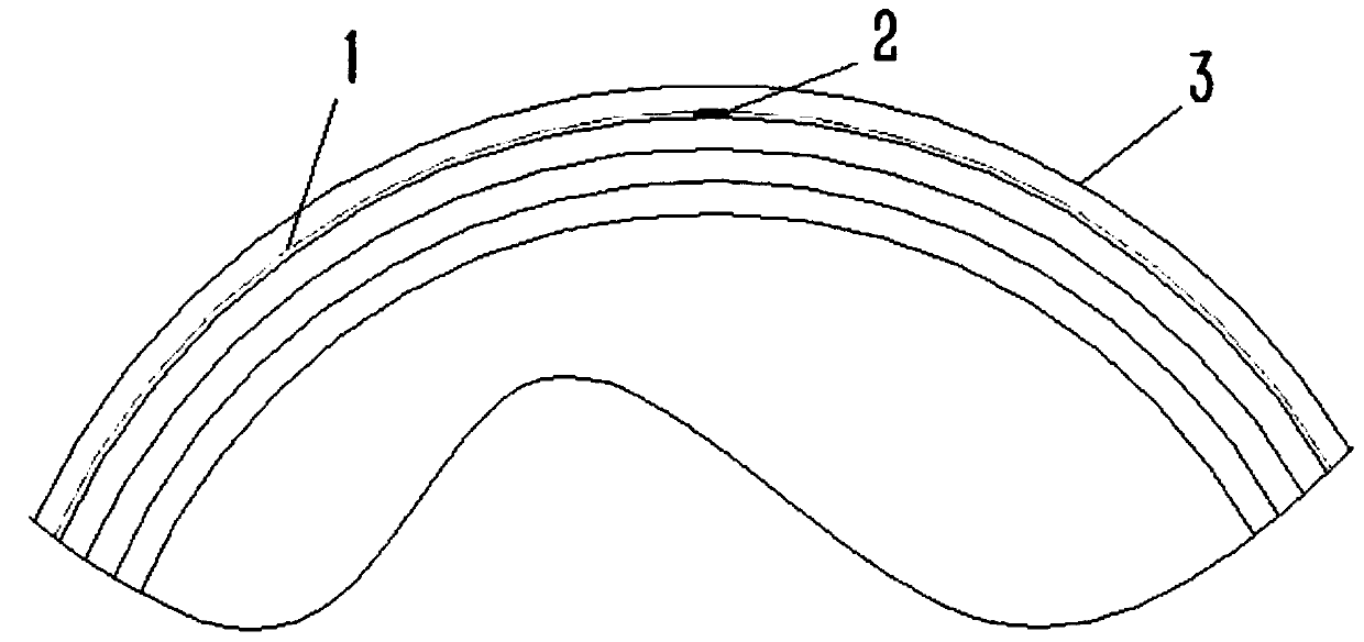
[0026] see figure 1 , the internal placement method of a sensor probe provided by the present invention will be described. The internal placement method of said a kind of Perth cavity pressure optical fiber 1 sensor probe is used to set the Perth cavity pressure sensor inside the coil 3, comprising the following steps:

[0027] 1) First, when winding the coil 3, select one or several turns of the coil; secondly, place the Perth cavity pressure optical fiber 1 from the head position of the selected coil, and set the Perth cavity pressure optical fiber 1 on it. The...


PUM


Abstract

The invention provides a method for internally placing a Fabry-Perot cavity pressure fiber sensor probe, which belongs to the technical field of transformers, and is used for setting a Fabry-Perot cavity pressure sensor probe inside a coil. When the coil is wound, a cavity pressure fiber is placed from an exit position, and wound by following electromagnetic wires. The Fabry-Perot cavity pressurefiber is placed between the electromagnetic wire turns and fixed by glue, and the Fabry-Perot pressure fiber and the electromagnetic wire are wrapped and fixed by using the binding material. When binding to the Fabry-Perot cavity pressure raster position, the electromagnetic wire insulation is removed, and the Fabry-Perot cavity pressure fiber and the electromagnetic wires are attached to each other and fixed. After the instant glue is solidified, the binding material is used for binding and fixing. The method is simple and reliable, and ensures that the Fabry-Perot cavity pressure fiber sensor probe and the installation position are adapted to each other, which can meet the needs of monitoring the transformer coil and ensure the performance and normal operation of the transformer, save time and labor, and improve work efficiency.

Description


Claims


Application Information

Patent Timeline
Owner BAODING TIANWEI GROUP TEBIAN ELECTRIC
Learn More