Three-phase PWM rectifier control method and system based on virtual synchronous machine

A technology of virtual synchronous machine and control method, which is applied in the direction of output power conversion device, conversion of AC power input to DC power output, electrical components, etc., and can solve problems such as incompetence in voltage support

Inactive Publication Date: 2019-04-26
STATE GRID JIANGSU ELECTRIC POWER CO LTD TAIZHOU POWER SUPPLY BRANCH +3
View PDF5 Cites 7 Cited by
  • Summary
  • Abstract
  • Description
  • Claims
  • Application Information

AI Technical Summary

Problems solved by technology

The virtual synchronous machine on the load side mostly adopts the current-controlled virtual synchronous machine technology, which has a better effect when applied to low-power loads, but when the power grid fluctuates or fails, it is difficult to be competent for the role of voltage support

Method used


Image

  • Three-phase PWM rectifier control method and system based on virtual synchronous machine
  • Three-phase PWM rectifier control method and system based on virtual synchronous machine
  • Three-phase PWM rectifier control method and system based on virtual synchronous machine

Examples


Embodiment 1

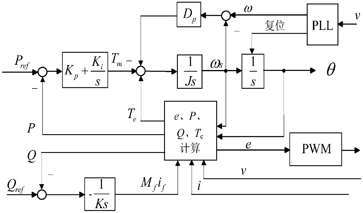
[0088] Such as figure 2 As shown, the direct power control method of the three-phase PWM rectifier based on the virtual synchronous machine includes the following contents:

[0089] For any moment, the active loop part adopts PI controller, which can realize the reference active power P ref There is no static difference following, the difference ΔP between the reference active power and the system output active power P is used as the input of the PI controller, and the output of the PI controller is the mechanical torque T m , and its specific calculation formula is:

[0090] T m = K p (P ref -P)+K i ∫(P ref -P)dt;

[0091] Among them, P ref is the reference active power, K p is the proportional coefficient of the PI controller, K i is the integral coefficient of the PI controller. The system output active power P is calculated by substituting the current power grid operating parameters obtained in real time into formula (5). The reference active power P ref Set t...

Embodiment 2

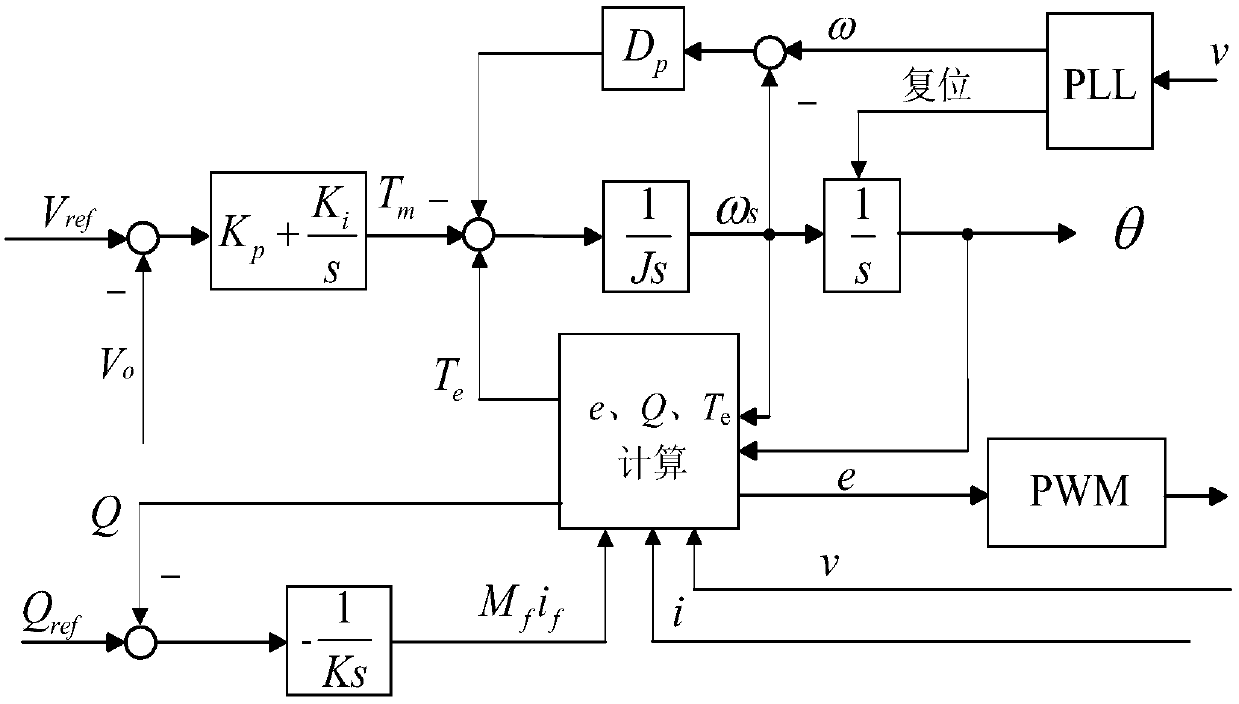
[0113] Such as image 3 As shown, the difference between this embodiment and Embodiment 1 is that in this embodiment, the control mode is DC constant voltage control, the active loop is a voltage loop, and the obtained current DC side output voltage V O and the reference DC voltage to calculate the excitation flux linkage. The specific process is: the DC side output voltage is obtained by sampling the DC side voltage; The calculation formula is:

[0114] T m = K p (V ref -V O )+K i ∫(V ref -V O )dt;

[0115] Among them, V ref is the reference DC voltage, V O is the output voltage of the DC side.

[0116] Based on the same inventive concept as the above method, the present invention also provides a three-phase PWM rectifier control system based on a virtual synchronous machine, including: a sampling module, a mechanical torque calculation module, an excitation flux linkage calculation module, and an AC power grid angular speed calculation module, an AC power grid an...


PUM


Abstract

The invention discloses a three-phase PWM rectifier control method and system. The three-phase PWM rectifier control method comprises the steps: aiming at any moment, operating parameters of an alternating-current power grid are obtained; the mechanical torque, excitation flux linkage and the alternating-current power grid angle rotating speed are calculated according to the operating parameters;the torque ptotic amount is calculated according to the alternating-current power grid angle rotating speed and the virtual rotating speed; the electromagnetic torque is calculated according to a three-phase current, the electric angle and the excitation flux linkage; the new virtual rotating speed is calculated according to the electromagnetic torque, the mechanical torque and the torque ptotic amount and serves as a feedback input value for calculating the torque ptotic amount of the next moment; the new electric angle is calculated according to the new virtual rotating speed and serves as afeedback input value for calculating the electromagnetic torque of the next moment; the virtual counter electromotive force is calculated according to the new electric angle, the new virtual rotatingspeed and the excitation flux linkage; and a modulating wave signal is calculated according to the virtual counter electromotive force. Under the situation of the stable state, the output voltage andpower can stably follow set values, and support is provided when the power grid fluctuates.

Description

technical field [0001] The invention belongs to the technical field of power system stability control, and in particular relates to a control method and system for a three-phase PWM rectifier based on a virtual synchronous machine. Background technique [0002] The three-phase PWM rectifier is the main power electronic device for the load to connect to the power grid. It has the advantages of bidirectional energy flow, unit power factor operation, output voltage and power controllable, etc. There are mainly two control schemes: direct power control and DC side voltage control. However, neither of these two control strategies can achieve the support and demand response functions for the grid, and it is difficult to perfectly connect with the smart grid. The load virtual synchronous machine technology has been widely concerned because it can control the load power in real time according to the grid frequency and voltage, and realize the friendly interaction between the load an...

Claims


Application Information

Patent Timeline
Patent Type & Authority Applications(China)
IPC IPC(8): H02M7/219
CPCH02M7/219
Inventor 吴争龙禹季昆玉贾俊翁蓓蓓蒋中军张卫国孙季泽汤延祺郑红娟王金明陈良亮李华
Owner STATE GRID JIANGSU ELECTRIC POWER CO LTD TAIZHOU POWER SUPPLY BRANCH
Why Eureka
Try Eureka