
Heat gun

A hot air, air channel technology, used in air heaters, fluid heaters, lighting and heating equipment, etc., can solve the problems of measuring temperature, laborious manipulation, etc.

Inactive Publication Date: 2019-06-28
ISABERG RAPID
View PDF6 Cites 3 Cited by
  • Summary
  • Abstract
  • Description
  • Claims
  • Application Information

AI Technical Summary

Problems solved by technology

However, in such hot air guns, as is known for example from DE 20 2012 102 739 U1, there is the difficulty that the temperature must be measured exactly at the point of impact of the air jet
For this the sensor must be pointed exactly at the point where the air jet hits, which in turn leads to laborious maneuvering

Method used


Image

  • Heat gun
  • Heat gun

Examples


Embodiment Construction

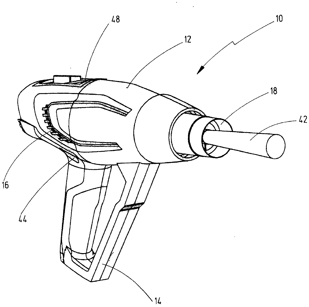
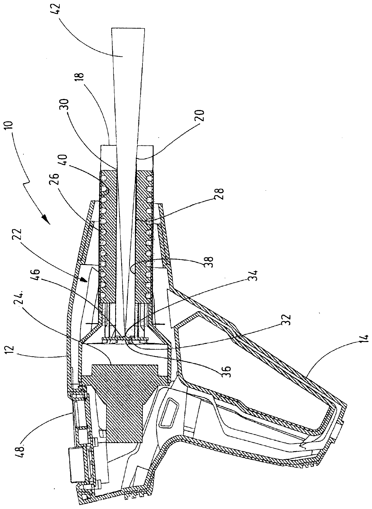
[0012] The hot air gun 10 shown in the drawing has a housing 12 with a handle 14 . The housing 12 also has an air inlet 16 in its rear region and an air outlet 18 on its front end, which is located partly at the figure 1 The right side visible in , is partially symmetrically located on the left side. An air duct 20 extends between the air inlet 16 and the air outlet 18, in which a hot air device 22 is arranged for sucking in ambient air via the air inlet 16, heating the ambient air and then distributing the hot air Blows through the air outlet 18 onto the workpiece to be heated. The hot air device 22 accordingly has a fan 24 and a heating unit 26 . The fan 24 is used to generate an air flow in the air channel 20 and the heating unit 26 is used to heat the air flowing past the heating unit.

[0013] Arranged in the air channel 20 is a measuring tube 28 whose front end 30 is open towards the air outlet 18 and which is arranged at a distance from the air outlet 18 so that it l...


PUM


Abstract

The invention relates to a heat gun (10) having: a housing (12) with an air duct (20) opening into an air outlet (18); a hot air device (22) arranged in the housing (12) for generating a hot air flowand for guiding the hot air flow through the air duct (20) via the air outlet (18) onto a workpiece; and a thermometer (36) with a temperature sensor (34) for contactless measurement of a surface temperature of the workpiece. According to the invention, a measuring tube (28) is arranged in the air duct (20), the forward end (30) of which tube is open and faces the air outlet (18) and in the rear end (32) of which tube the temperature sensor (34) is arranged.

Description

technical field [0001] The invention relates to a hot air gun according to the preamble of claim 1 . Background technique [0002] Hot air guns are used to heat workpieces in a targeted manner, for example to deform a workpiece or to weld it to another workpiece, to apply a film to or remove a film from a workpiece or to dry a workpiece or to accelerate a chemical process. The hot air gun has a housing in which a hot air device is arranged, which sucks in ambient air via an air inlet in the housing, heats it up and conducts it via an air duct via an air outlet to on the workpiece. Typical hot air temperatures fall in the range of several hundred degrees Celsius. The temperature actually achieved on the surface of the workpiece depends not only on the temperature of the hot air and the air flow rate, but also largely on the distance between the air outlet and the surface of the workpiece. The user of the hot air gun must therefore develop a good feel for this in practice, ...

Claims


Application Information

Patent Timeline
Patent Type & Authority Applications(China)
IPC IPC(8): F24H3/04
CPCF24H3/0423G01J5/0003G01J5/025G01J5/0265G01J5/0818G01J5/0893G01J5/0808
Inventor M·霍尔格松A·爱德华松
Owner ISABERG RAPID
Learn More