Foldable photovoltaic power generation mechanism

A photovoltaic power generation and photovoltaic panel technology, which is applied in the field of foldable photovoltaic power generation mechanisms, can solve the problems of inconvenient movement and time-consuming assembly, and achieve the effects of easy transportation, high assembly efficiency, and fast deformation speed

Active Publication Date: 2019-07-02
浙江美尚光伏有限公司
View PDF3 Cites 2 Cited by
  • Summary
  • Abstract
  • Description
  • Claims
  • Application Information

AI Technical Summary

Problems solved by technology

It can be used for military and civilian life in remote areas without electricity, such as plateaus, islands, pastoral areas, and border posts, and can also be used as a solar power source for residential users; the assembly of photovoltaic panels usually requires professionals, and when large-area solar panels are required, they need to be built. Large-area metal brackets take a long time to assemble and are not easy to move after assembly

Method used


Image

  • Foldable photovoltaic power generation mechanism
  • Foldable photovoltaic power generation mechanism
  • Foldable photovoltaic power generation mechanism

Examples


specific Embodiment approach 1

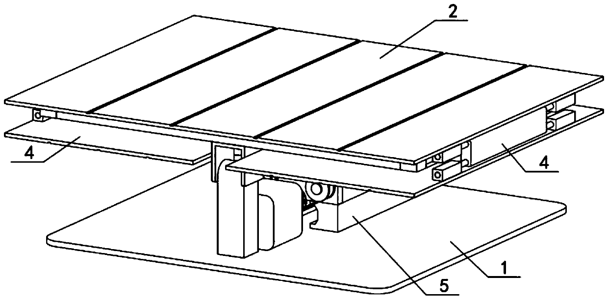
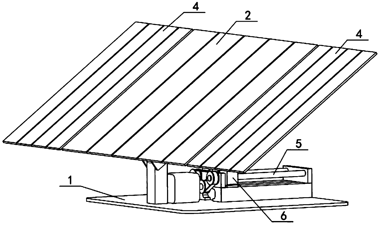
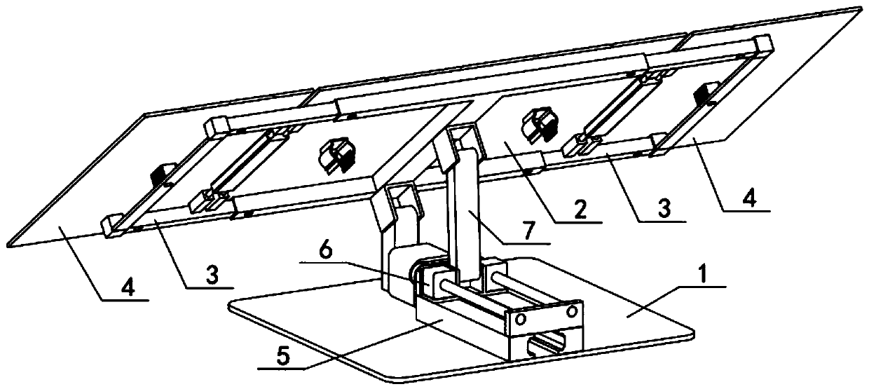
[0030] like Figure 1-10 As shown, the foldable photovoltaic power generation mechanism includes an installation base 1, a photovoltaic panel I2, a telescopic frame 3, a photovoltaic panel II4, a track 5, a displacement member 6 and a connecting rod 7, and the installation base 1 is rotatably connected with a photovoltaic panel I2, The left and right sides of the photovoltaic panel Ⅰ2 are slidingly connected with the telescopic frame 3, the photovoltaic panel Ⅱ4 is rotatably connected with the photovoltaic panel Ⅰ2, the track 5 is fixedly connected to the installation base 1, the track 5 and the installation base 1 are connected by belt transmission, and the displacement member 6 is connected to the installation base 1. The track 5 is slidably connected, the displacement member 6 is rotatably connected to one end of the connecting rod 7 , and the other end of the connecting rod 7 is rotatably connected to the photovoltaic panel I2.

specific Embodiment approach 2

[0032] like Figure 1-10 As shown, the installation base 1 includes a touch plate 1-1, a bearing seat 1-2, a motor 1-3 and a pulley I1-4, and the rear end of the touch plate 1-1 is fixedly connected with a bearing seat 1-2 , The motor 1-3 is fixedly connected to the touch plate 1-1, and the pulley I1-4 is fixedly connected to the output shaft of the motor 1-3. The height of the bearing housing 1-2 should meet the requirement that when the inclination angle of the main body of the photovoltaic panel I2-9 reaches the maximum value, when the main body of the photovoltaic panel II4-1 is turned and exhibited, the main body of the photovoltaic panel II4-1 will not touch the floor 1 -1, used to make the photovoltaic panel main body II4-1 rotate 180 degrees smoothly.

specific Embodiment approach 3

[0034] like Figure 1-10As shown, the photovoltaic panel I2 includes a connecting part I2-1, a square tube 2-2, an installation hole I2-3, an installation hole II2-4, an axle seat I2-5, an axle I2-6, an axle seat II2-7, Shaft II 2-8, photovoltaic panel main body I 2-9, connection sleeve I 2-10, connection sleeve II 2-11, and snap handle 2-12, the front and rear ends of the connection part I 2-1 are fixedly connected with square pipes 2-2 At the middle end of the two square tubes 2-2, the lower ends on the left side are provided with installation holes I2-3, and the lower ends on the right side of the two square tubes 2-2 are provided with installation holes II2-4, and the shaft seats I2-5 are fixed Connected in the middle of the lower end of the square tube 2-2 at the rear end, shaft I2-6 is fixedly connected to shaft seat I2-5, shaft seat II2-7 is fixedly connected to the front side of the lower end of connection part I2-1, shaft seat II2- 7 is fixedly connected with the sha...


PUM


Abstract

The invention relates to a power generation mechanism, and particularly to a foldable photovoltaic power generation mechanism. The foldable photovoltaic power generation mechanism comprises a mountingbase, a photovoltaic panel I, a telescopic frame, a photovoltaic panel II, a track, a displacement member and a connecting rod. The foldable photovoltaic power generation mechanism can be folded or unfolded primarily by using the rotatable photovoltaic panel II. By using the connecting rod having a movable one end, the foldable photovoltaic power generation mechanism can be folded or unfolded secondarily. The combination of the telescopic frame and an engagement hand facilitates the folding or unfolding of the foldable photovoltaic power generation mechanism, so that the foldable photovoltaicpower generation mechanism has a fast deformation speed and high assembly efficiency. After folded, the foldable photovoltaic power generation mechanism is easy to move by means of universal wheels,and is reduced in occupied space in order to be easy to package and transport. When the foldable photovoltaic power generation mechanism is unfolded and installed, there is no need to build a bracketwith a large amount of manpower for assembly.

Description

technical field [0001] The present invention relates to a power generating mechanism, more specifically a foldable photovoltaic power generating mechanism. Background technique [0002] A photovoltaic panel, also known as a solar panel, is an assembly of several solar cell components assembled on a board in a certain way, usually as a unit of a photovoltaic array. It can be used for military and civilian life in remote areas without electricity, such as plateaus, islands, pastoral areas, and border posts, and can also be used as a solar power source for residential users; the assembly of photovoltaic panels usually requires professionals, and when large-area solar panels are required, they need to be built. Large-area metal brackets take a long time to assemble and are not easy to move after assembly. Contents of the invention [0003] The purpose of the present invention is to provide a foldable photovoltaic power generation mechanism, which can be compressed and folded ...

Claims


Application Information

Patent Timeline
IPC IPC(8): H02S30/20H02S20/30F24S25/67F24S30/40
CPCH02S20/30H02S30/20Y02E10/50
Inventor 不公告发明人
Owner 浙江美尚光伏有限公司
Why Eureka
Try Eureka