
Simplified grid deformation method and device based on microcomputable

A technology for mesh deformation and algorithm simplification, applied in the computer field

Active Publication Date: 2021-05-18
GUILIN UNIV OF ELECTRONIC TECH
View PDF3 Cites 0 Cited by
  • Summary
  • Abstract
  • Description
  • Claims
  • Application Information

AI Technical Summary

Problems solved by technology

Because the existing 3D mesh deformation method has not been introduced into deep learning, and the existing mesh deformation method only edits on a 3D mesh

Method used


Image

  • Simplified grid deformation method and device based on microcomputable
  • Simplified grid deformation method and device based on microcomputable
  • Simplified grid deformation method and device based on microcomputable

Examples


Embodiment 1

[0073] According to an embodiment of the present invention, a simplified mesh deformation device based on differentiable calculation is provided, Figure 8 It is a schematic diagram of a simplified mesh deformation device based on differentiable calculation in Embodiment 1 of the device of the present invention, as Figure 8 As shown, the simplified mesh deformation device based on differentiable calculation according to the embodiment of the present invention specifically includes:

[0074] A subdivision module 80, configured to subdivide the initial grid to obtain a source grid; the subdivision module 80 is specifically used for:

[0075] Loop subdivides the initial grid to obtain the source grid. The initial grid is a simple cube or dodecahedron. Through Loop subdivision, 1-4 triangular patches are used to generate only new edge points and new vertices. Calculate, and then connect through topological rules, and subdivide to generate an approximate triangular mesh;

[0076...

Embodiment 2

[0096] Embodiments of the present invention provide a simplified mesh deformation device based on differentiable calculations, such as Figure 9 As shown, it includes: a memory 90, a processor 92, and a computer program stored on the memory 90 and operable on the processing 52. When the computer program is executed by the processor 92, it is implemented as in the method embodiment. steps described.

[0097] Device embodiment two

[0098] An embodiment of the present invention provides a computer-readable storage medium, where a program for realizing information transmission is stored on the computer-readable storage medium, and when the program is executed by the processor 92, the steps described in the method embodiments are implemented.

[0099] The computer-readable storage medium described in this embodiment includes but is not limited to: ROM, RAM, magnetic disk or optical disk, and the like.

[0100] Obviously, those skilled in the art should understand that each modul...


PUM


Abstract

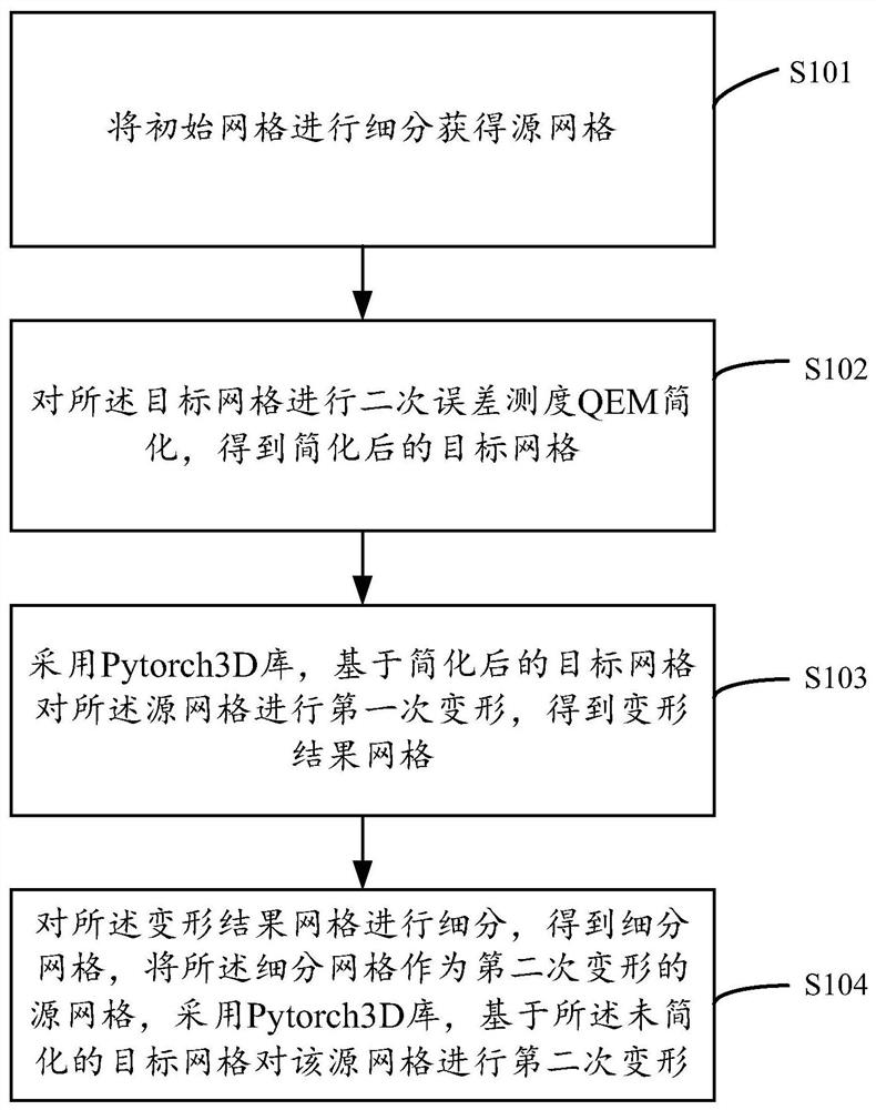
The invention discloses a simplified grid deformation method and device based on microcomputable. The method comprises the following steps: subdividing an initial grid to obtain a source grid; performing secondary error measurement (QEM) simplification on the target grid to obtain a simplified target grid; adopting a Pytorch3D library to perform first deformation on the source grid based on the simplified target grid to obtain a deformation result grid; and subdividing the deformation result grid to obtain a subdivided grid, taking the subdivided grid as a source grid for secondary deformation, and adopting a Pytorch3D library to perform secondary deformation on the source grid based on the unsimplified target grid. According to the method, the grid deformation speed is increased. The target grid is simplified, so that the grid deformation time is shortened, and a better grid deformation effect can be obtained to a certain extent.

Description

technical field [0001] The invention relates to the field of computer technology, in particular to a simplified grid deformation method and device based on differentiable calculations. Background technique [0002] Bringing 3D into computer vision has been attracting a lot of attention. Mesh deformation is a research hotspot in the field of computer animation and geometric modeling, and many techniques have been developed to provide natural-looking deformations. What meshes require is a local description of a shape that does not depend on the shape's specific location in Euclidean space. In the early days, free deformation technology was the main mesh deformation technology. Its algorithm was simple, and it was a point-by-point operation. A large amount of manual adjustment was required for the mesh with rich local details. The multi-resolution grid editing technology overcomes the shortcomings of the free deformation technology in local detail editing, and can be edited i...

Claims


Application Information

Patent Timeline
Patent Type & Authority Applications(China)
IPC IPC(8): G06T17/20
CPCG06T17/20G06T2200/04Y02T90/00
Inventor 史卓曾树珍
Owner GUILIN UNIV OF ELECTRONIC TECH
Learn More