
Operating method for injection moulding machine

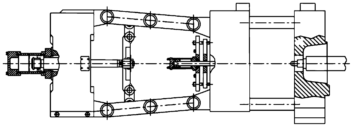
An operation method and injection molding machine technology, applied in the field of injection molding machine equipment, can solve the problems of large damage, large vibration and noise, and long energy consumption of various parts of the injection molding machine, so as to reduce deformation time, reduce vibration and noise, and increase service life Effect

Active Publication Date: 2019-11-26
宁波市北仑复力机械有限公司
View PDF1 Cites 0 Cited by
  • Summary
  • Abstract
  • Description
  • Claims
  • Application Information

AI Technical Summary

Problems solved by technology

[0002] The double toggle clamping device usually used in the existing plastic injection molding machine, refer to figure 1 As shown in , it is a mold clamping structure of injection molding machine disclosed in the document "Working Principle and Structure of Injection Molding Machine" in Baidu library. During the mold clamping process, the piston rod of the mold opening and closing cylinder pushes the cross thrust seat to move. Then the connecting rod is pushed by the cross thrust seat to straighten the connecting rod to achieve the effect of locking the mold. At this time, the template, connecting rod, lock shaft, cross thrust seat, tie rod and other components of the injection molding machine and the mold will be deformed, and the clamping force The higher the value, the greater the deformation, the longer the force time, the greater the damage to the parts of the injection molding machine, and the longer the force time, the greater the waste of energy consumption, and the vibration and noise generated during the mold opening process. will be bigger

Method used


Image

  • Operating method for injection moulding machine
  • Operating method for injection moulding machine

Examples


Embodiment Construction

[0020] In order to make the technical means, creative features, goals and effects achieved by the present invention easy to understand, the following embodiments are combined with the accompanying drawings to illustrate the present invention in detail. And define the direction from the fixed template to the movable template as the direction from front to back.

[0021] refer to figure 2 As shown in , in the operation method of the injection molding machine provided by the present invention, the injection molding machine includes a mold opening and closing cylinder, an injection assembly, a fixed platen, a movable platen, a rear platen, and a mold located between the fixed platen and the movable platen. There is a connecting cross thrust seat and connecting rod between the formwork and the rear formwork, and the piston end of the mold opening and closing cylinder passes through the back formwork to connect to the cross thrust seat, and the two ends of the connecting rod are re...


PUM


Abstract

The invention discloses an operating method for an injection moulding machine. The operating method comprises the following steps including: step a, performing mould-closing operation by the injectionmoulding machine; step b, performing high-pressure mould locking action by the injection moulding machine, further pushing a cross thrust base to move forwards through a piston of a mould opening andclosing oil cylinder, and locking a movable moulding board; step c, performing injecting action by an injecting assembly; step d, controlling the mould opening and closing oil cylinder to operate bya hydraulic oil path of a mould opening valve in the injection moulding machine, driving the cross thrust base to retract backwards by a preset distance n smaller than a mould opening distance m, andkeeping a high-pressure mould locking state of the movable moulding board by the mould opening and closing oil cylinder and a connecting rod; step e, performing storage action by the injecting assembly; and step f, performing mould-opening action, de-moulding and performing the step a. According to the technical scheme adopted by the invention, mould opening action with a short distance is performed once after injecting action and before storage action, deformation time of each mould locking part of the injection moulding machine and a mould is reduced, the service life can be prolonged, vibrations and noises are reduced, and energy consumption is reduced.

Description

technical field [0001] The invention relates to the technical field of injection molding machine equipment, in particular to an operation method of an injection molding machine. Background technique [0002] The double toggle clamping device usually used in the existing plastic injection molding machine, refer to figure 1 As shown in , it is a mold clamping structure of injection molding machine disclosed in the document "Working Principle and Structure of Injection Molding Machine" in Baidu Library. During the mold clamping process, the piston rod of the mold opening and closing cylinder pushes the cross thrust seat to move. Then the connecting rod is pushed by the cross thrust seat to straighten the connecting rod to achieve the effect of locking the mold. At this time, the template, connecting rod, lock shaft, cross thrust seat, tie rod and other components of the injection molding machine and the mold will be deformed, and the clamping force The higher the value, the gr...

Claims


Application Information

Patent Timeline
Patent Type & Authority Applications(China)
IPC IPC(8): B29C45/68
CPCB29C45/681
Inventor 张宏斌丁晓磊
Owner 宁波市北仑复力机械有限公司
Learn More