
Fluid filter

A filter and fluid technology, applied in the field of filters, can solve the problems of reduced filter performance, material waste, and affecting the service life of filters

Inactive Publication Date: 2020-10-23
李斌
View PDF0 Cites 0 Cited by
  • Summary
  • Abstract
  • Description
  • Claims
  • Application Information

AI Technical Summary

Problems solved by technology

The filter element is the most prone to blockage under long-term use, and impurities will accumulate on the filter element, causing the blockage of the filter element to greatly reduce the filtration performance, which will directly affect the service life of the filter
The existing filters on the market cannot replace the filter elements individually, and the entire filter can only be discarded, resulting in a serious waste of materials
[0003] At the same time, when the fluid medium with a certain pressure passes through the filter element, due to the resistance of the filter element, a pressure difference will be generated on the inner and outer walls of the filter element, and the pressure difference will cause a small amount of broken fibers in the filter element to flow out with the fluid medium, thereby affecting the filter performance. clear effect; for this reason, the present invention proposes a kind of fluid filter

Method used


Image

  • Fluid filter
  • Fluid filter
  • Fluid filter

Examples


Embodiment approach

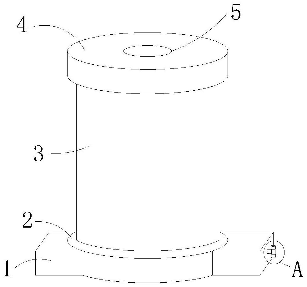
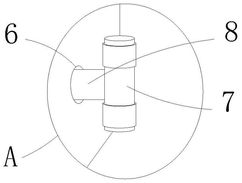
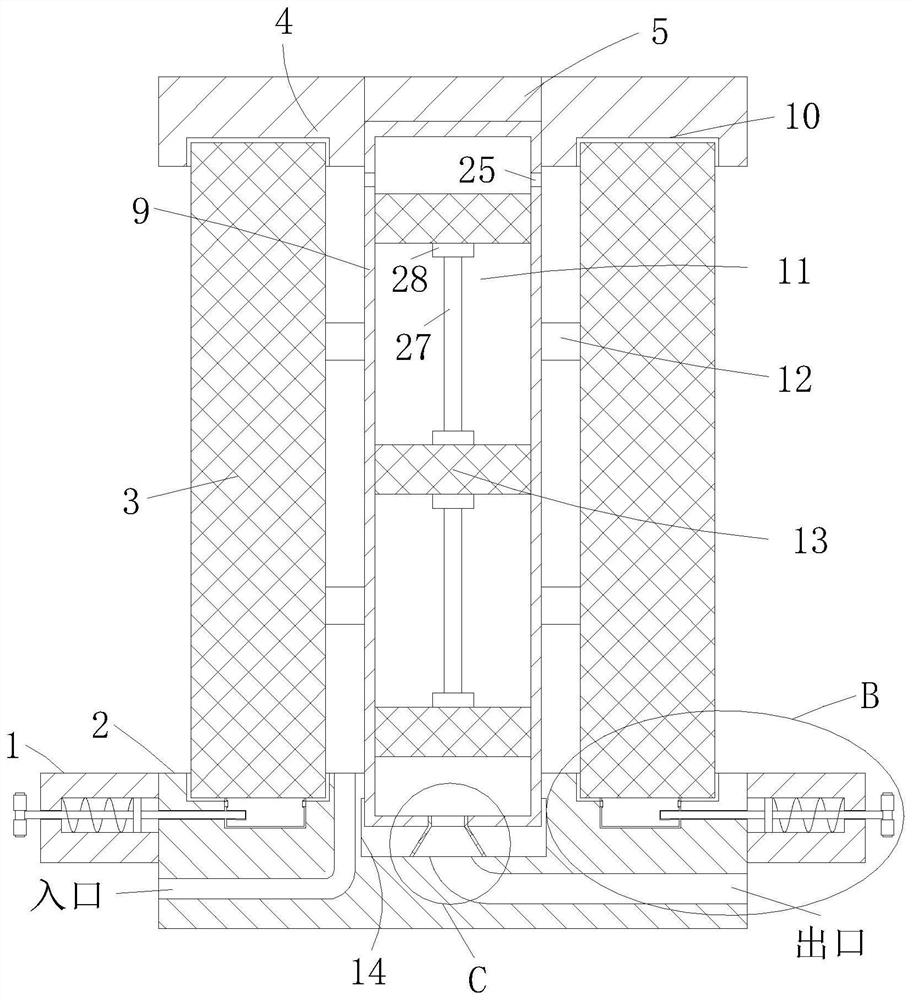
[0024] As an embodiment of the present invention, a number of filter chambers 11 are provided on the side of the connecting body 9; at least three matching filter screens 13 are installed in the filter chamber 11, and the top of the filter chamber 11 A group of first through holes 25 are provided, and a second through hole 26 is provided at the lower end of the filter chamber 11; the second through holes 26 communicate with the outlet; cavity; the number of meshes of the filter gauze 13 gradually increases from top to bottom. When working, when the fluid medium with a certain pressure passes through the filter element 3, due to the resistance of the filter element 3, a pressure difference will be generated on the inner and outer walls of the filter element 3, and the pressure difference will cause a small amount of broken fibers in the filter element 3 to flow out with the fluid medium. The filtering effect of the filter, and through opening a number of filtering through cavit...


PUM


Abstract

The invention relates to the technical field of filters, in particular to a fluid filter which comprises a lower cover, a threaded groove is formed in the upper surface of the lower cover, a connecting body is in threaded connection with the interior of the threaded groove, an upper cover is arranged above the lower cover, and a threaded through cavity is formed in the upper surface of the upper cover; when a filter element is damaged or blocked, the upper cover is rotated, clamping rods are pulled, the horizontal movement of the clamping rods can drive the horizontal movement of a sliding block; extrusion of springs is realized, one end, positioned in a clamping groove, of the clamping rod is drawn out from the clamping groove; therefore, a clamping block can be drawn out of the groove;therefore, the lower end of the filter element can be drawn out from an annular groove I of the lower cover; during installation, the lower end of the filter element is inserted into the annular groove I in a penetrating mode, the two clamping blocks are inserted into the groove in a penetrating mode respectively, the clamping rods are loosened, the springs elastically push the sliding blocks to move horizontally, water movement of the sliding blocks drives the clamping rods to move horizontally, the clamping rods are inserted into the clamping grooves in a penetrating mode to fix the filter element, and therefore the filter element is easy and fast to disassemble and install, and material waste is avoided.

Description

technical field [0001] The invention relates to the technical field of filters, in particular to a fluid filter. Background technique [0002] The filter includes a support assembly and a filter element made of paper material for filtering impurities. The filter element is the most prone to clogging under long-term use. Impurities will accumulate on the filter element, which will cause the filter element to clog and greatly reduce the filtration performance, which will directly affect the service life of the filter. For existing filters on the market, the filter elements cannot be replaced individually, and the entire filter can only be discarded, resulting in a serious waste of materials. [0003] At the same time, when the fluid medium with a certain pressure passes through the filter element, due to the resistance of the filter element, a pressure difference will be generated on the inner and outer walls of the filter element, and the pressure difference will cause a sma...

Claims


Application Information

Patent Timeline
IPC IPC(8): B01D29/56B01D29/96B01D46/00
CPCB01D29/56B01D29/96B01D46/62B01D46/88
Inventor 李斌陈一帆
Owner 李斌
Learn More