
Casting roll and method for casting metal strip with crown control

A technology of casting metal and controlling rolls, which is applied in the field of casting metal strips, can solve problems such as significant changes in convexity and unpredictable shape differences, and achieve the effect of saving external sensors and temperature sensors

Active Publication Date: 2019-09-06
SIEMENS AG OESTERR
View PDF7 Cites 0 Cited by
  • Summary
  • Abstract
  • Description
  • Claims
  • Application Information

AI Technical Summary

Problems solved by technology

However, the difference between the shape of the casting surface of the casting rolls when cold and between casting conditions is diffi

Method used


Image

  • Casting roll and method for casting metal strip with crown control
  • Casting roll and method for casting metal strip with crown control
  • Casting roll and method for casting metal strip with crown control

Examples


Example Embodiment

[0074] Reference now figure 1 , Figure 2A with Figure 2B , A twin-roll casting machine including a main machine frame 10 is illustrated, which stands up from the factory floor and supports a pair of reverse-rotatable casting rolls 12 in a module installed in the roll box 11. The casting roll 12 is installed in the roll box 11 for easy handling and movement, as described below. The roller box 11 helps to prepare the casting roller 12 for casting as a unit to quickly move from the set position to the operating casting position in the casting machine, and to easily remove the casting roller 12 from the casting position when the casting roller 12 is to be replaced . There is no desired specific configuration of the roll box 11 as long as it performs the function of facilitating the movement and positioning of the casting roll 12 as described herein.

[0075] The casting equipment for continuous casting of thin steel strip includes a pair of counter-rotating casting rolls 12 having...


PUM


Abstract

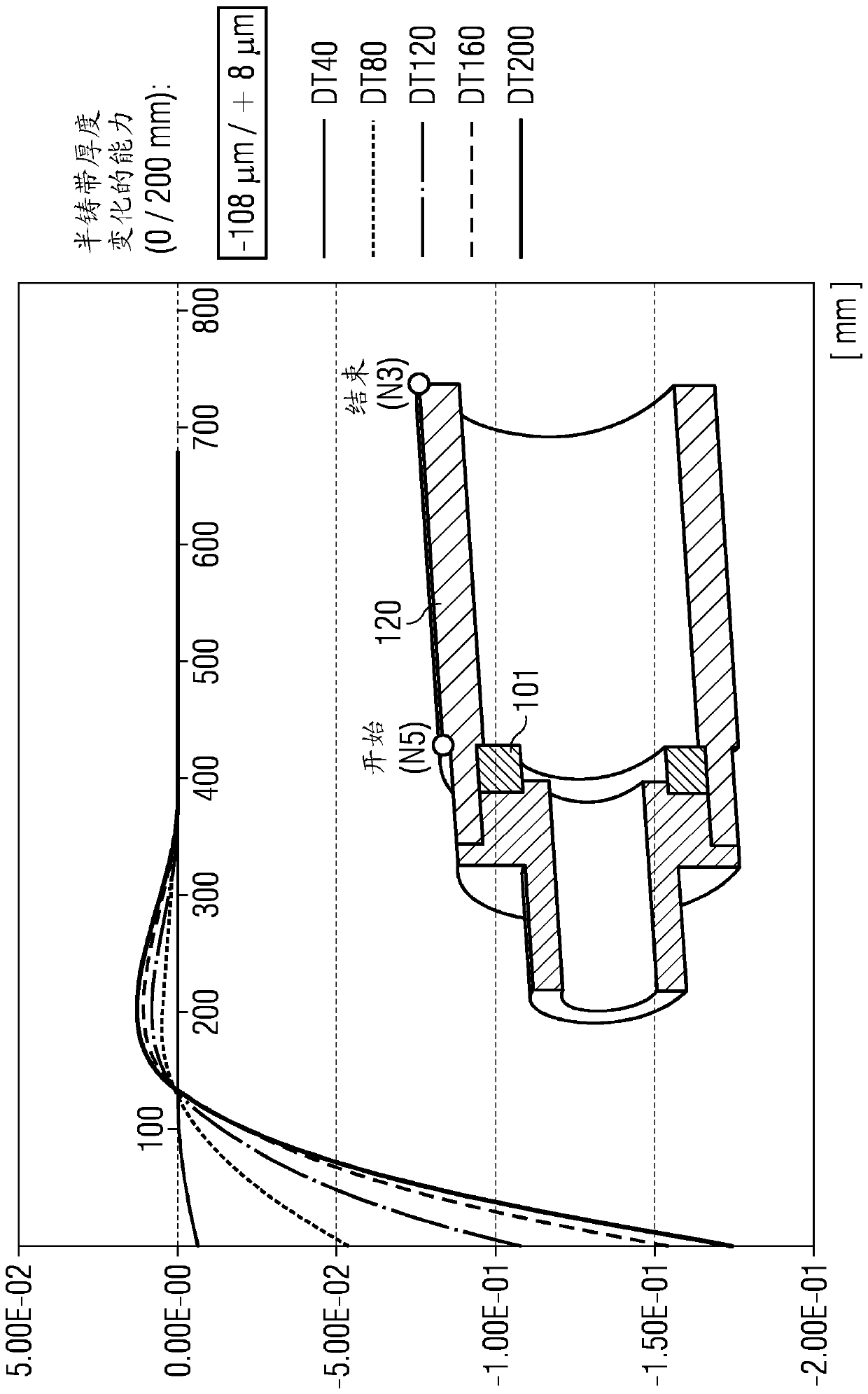
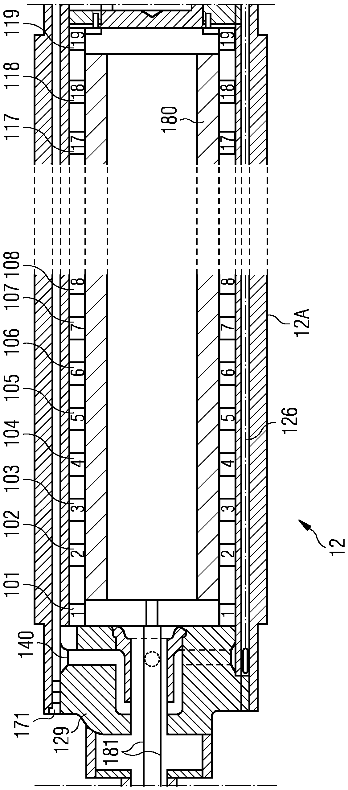
The invention relates to a casting roll (12), for the casting of metal strip (21) by continuous casting in a twin roll caster, having a casting surface (12A) formed by a substantially cylindrical tube(120), having axially symmetric expansion elements, such as expansion rings (101-119), arranged within and adjacent the cylindrical tube (120), each expansion element spaced from another expansion element, and the expansion elements adapted to increase in radial dimension causing the cylindrical tube to expand changing roll crown of the casting surfaces of the casting rolls and thickness profileof the cast strip during casting, whereas a multitude of axially symmetric expansion elements, such as expansion rings (101-119), are distributed along the entire length of the cylindrical tube (120)and a power switch is situated in or on the casting roll (12) in order to switch electrical power supply of the expansion elements (101-119) from one or more expansion elements to one or more other expansion elements. The method of continuously casting thin strip by controlling roll crown is characterized in that at least one expansion element is increased in radial dimension, preferably by heating, causing the cylindrical tube (120) to expand while at least one other expansion element is not increased in radial dimension.

Description

technical field [0001] The present invention relates to the casting of metal strip by continuous casting in a twin roll caster. [0002] In particular, the invention relates to a casting roll for casting metal strip by continuous casting in a twin roll caster, the casting roll: [0003] - having a casting surface formed by a substantially cylindrical tube, [0004] - having axisymmetric expansion elements, such as expansion rings, arranged within and adjacent to the cylindrical tube, each expansion element being spaced apart from the other, and the expansion elements adapted to increase in radial size resulting in a cylindrical The tube expands, changing the roll crown of the casting surface of the casting rolls and the thickness profile of the cast strip during casting. [0005] The thickness of the casting roll tube is often less than 120 mm, such as less than 100 mm or even less than 80 mm. The casting roll tube material is generally selected from the group comprising co...

Claims


Application Information

Patent Timeline
IPC IPC(8): B22D11/06B22D11/16C03B35/18
CPCB22D11/0622B22D11/0651B22D11/168B22D11/0665
Inventor G.霍亨比希勒
Owner SIEMENS AG OESTERR
Learn More