Flexible joint

A technology of flexible joints and curved segments, applied in surgical robots and other directions, can solve problems such as unpredictable deformation effects, uncertain deformation patterns, and uneven materials.

Active Publication Date: 2019-10-22
SUZHOU MAILAN MEDICAL TECH CO LTD
View PDF10 Cites 3 Cited by
  • Summary
  • Abstract
  • Description
  • Claims
  • Application Information

AI Technical Summary

Problems solved by technology

[0003] like figure 1 As shown, an existing flexible joint has the following structure: a flexible tube 100 is provided with staggered notches 101 arranged on the side wall of the flexible tube 100, and bending deformation occurs when the flexible tube 100 is stressed; however, the flexible tube 100 The position of the center of the bending deformation is uncertain, and its material may not be uniform. In this case, the deformation state is also uncertain. Usually, the deformation effect cannot meet expectations

Method used


Image

  • Flexible joint
  • Flexible joint
  • Flexible joint

Examples


no. 1 example

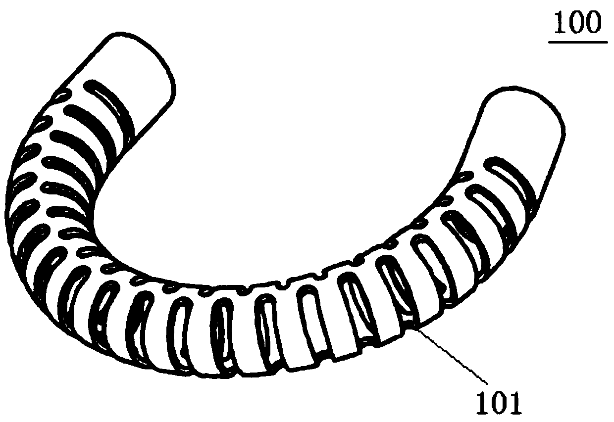
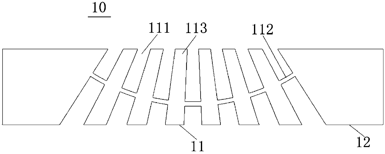
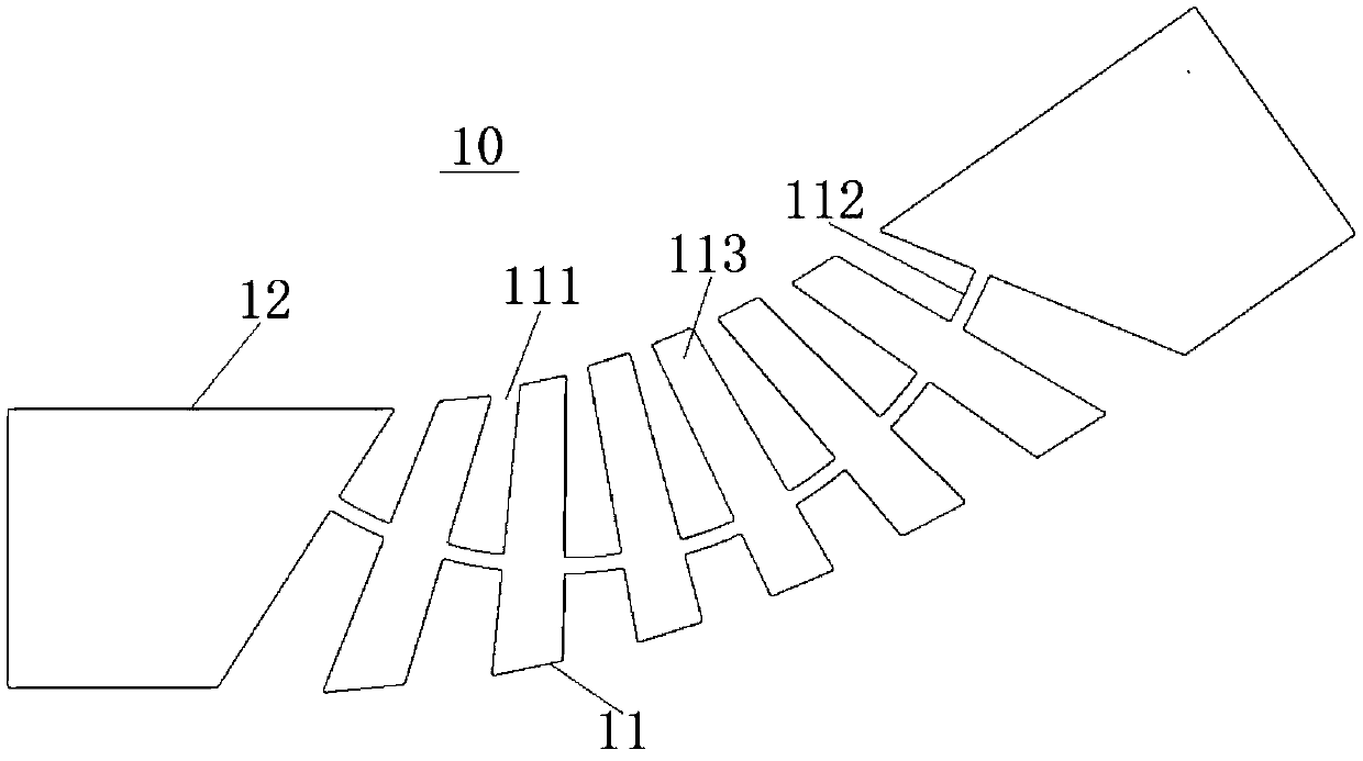
[0056] Please refer to Figure 2 to Figure 3, in this embodiment, the flexible joint unit 10 can have seven bending sections, each of which includes a radial notch 111 and a connecting rib 112, and an annular band 113 is formed between two adjacent bending sections so as to pass through the ring The connecting ribs 112 of two adjacent bending sections are connected together by the endless belt 113 . The annular band 113 is formed by a part of the remaining side wall, which surrounds the circumferential direction of the curved section 11, and correspondingly, the connecting rib 112 is formed by another part of the remaining side wall, which is formed by the other part of the remaining side wall on the curved section 11. connection between the two ends.

[0057] Each of the annular belts 113 of the flexible joint unit 10 is grouped to form a radially inner annular belt system and a radially outer annular belt system. Each of the radially inner annular belt system and the radial...


PUM


Abstract

The invention provides a flexible joint including at least one flexible joint unit. The flexible joint unit has a side wall and a hollow structure extending along a predetermined axis and surrounded by the side wall. A part of the side wall is cut to form a bending section which is used for forming a predetermined bending posture; the bending section has at least one bending joint, the bending joint has a radial notch and a connecting rib, and the radial notch is formed by cutting the side wall; the connecting rib is formed by the remaining side wall connected between two ends of the bending section. When the flexible joint is not stressed, the connecting rib forms an arc shape relative to the axis. After two ends of the flexible joint are stressed, a relatively definite and predictable bending path can be generated, the flexible joint is bent in a predetermined direction through the arc-shaped connecting rib, and the predictable bending posture can be obtained.

Description

technical field [0001] The invention relates to the technical field of medical equipment, in particular to a medical flexible joint. Background technique [0002] In medical clinical applications, flexible joints are often used in surgical equipment to assist doctors to extend surgical equipment into the human body to perform surgical operations. Specifically, the surgical device includes a top end and a tail end, the top end is used to penetrate into the human body, and the tail end is used to be held. The top is usually provided with flexible joints and specific surgical equipment, such as endoscopes, etc. are installed through the flexible joints. When the doctor needs to perform surgical repair on the target position in the human body, he can change the posture of the flexible joint by operating the tail end of the surgical device so as to adjust the angle and position of the surgical device at the top. [0003] Such as figure 1 As shown, an existing flexible joint ha...

Claims


Application Information

Patent Timeline
Patent Type & Authority Applications(China)
IPC IPC(8): A61B34/30
CPCA61B34/30A61B2034/301A61B2034/306
Inventor 周啸波蓝青
Owner SUZHOU MAILAN MEDICAL TECH CO LTD
Why Eureka
Try Eureka