Supercharge Your Innovation With Domain-Expert AI Agents!

Back patting machine

A technology of electric motors and motor shafts, which can be used in physical therapy, vibration massage, massage auxiliary products, etc., and can solve troublesome and laborious problems

Inactive Publication Date: 2019-11-05
毛勇军
View PDF0 Cites 0 Cited by
  • Summary
  • Abstract
  • Description
  • Claims
  • Application Information

AI Technical Summary

Problems solved by technology

[0003] In order to overcome the troublesome and labor-intensive shortcomings of the existing back-beating methods, the present invention provides a back-beating machine, which is convenient and labor-saving for back-beating

Method used


Image

  • Back patting machine
  • Back patting machine
  • Back patting machine

Examples


Embodiment Construction

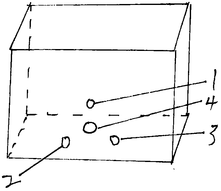
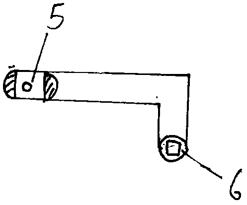
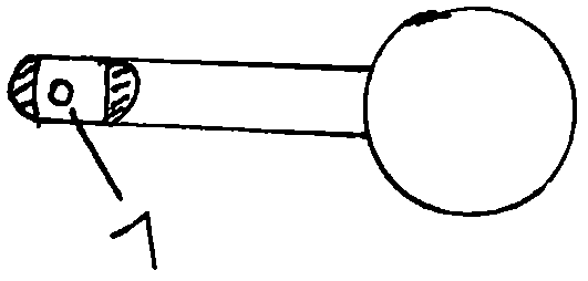
[0013] Make a rectangular box out of plastic figure 1 , wherein one of the narrower faces is open, and there are four holes (1), (2), (3), (4) on a face adjacent to the open face. Make another 7-shaped metal rod such as figure 2 , one of which is longer and one shorter, and the short one is a square tube (6) inside, and the end of the long one is 1 cm long and cut in half, and has a small hole (5 mm) at 4 mm from the end. ). Make another metal rod such as image 3 , one end of which is equipped with a rubber ball, the other end has a length of 1 cm and is cut in half, and there is a small hole (7) at 4 mm from the end. The end of the motor shaft is a quadrangular cylinder (8) such as Figure 4 . Make a long tube out of plastic, such as Figure 5 , wherein one end is open, and there are three elliptical small pieces on its edge, a small hole (9), (10), (11) is arranged on each small piece, and the other end has a cover. Bundle Figure 4 The motor in the Figure 5 and ...


PUM


Abstract

The invention discloses a back patting machine which is labor-saving and convenient. According to the back patting machine, a motor is mounted on a rectangular box with an opening in one of the side surfaces. Two hard rods are connected together, for the other two ends of the two hard rods, a ball is installed at one end of one of the two hard rods, and one end of one of the two hard rods is connected to a motor shaft.

Description

technical field [0001] The invention relates to a back-beating device, in particular to a back-beating machine which is convenient and labor-saving. Background technique [0002] At present, back-beating is usually performed by one person by hand for another person, or by himself with a rubber hammer, which is both troublesome and laborious. Contents of the invention [0003] In order to overcome the troublesome and labor-intensive shortcomings of the existing back-beating methods, the present invention provides a back-beating machine, which is convenient and labor-saving for back-beating. [0004] The technical solution adopted by the present invention to solve its technical problems is: make a rectangular box with a side opening, a motor is installed on a side adjacent to the side of the opening, and a hard rod vertically connected with the motor shaft is arranged in the box , there is a small hole at the other end of the hard rod across the hard rod, and there is also ...

Claims


Application Information

Patent Timeline
Patent Type & Authority Applications(China)
IPC IPC(8): A61H23/02
CPCA61H23/02
Inventor 毛勇军
Owner 毛勇军
Features
  • R&D
  • Intellectual Property
  • Life Sciences
  • Materials
  • Tech Scout
  • Unparalleled Data Quality
  • Higher Quality Content
  • 60% Fewer Hallucinations
Learn More