
Eureka
For R&D, Eureka makes reading and utilizing patents & technical documents easy.
Eureka AIR
Designed for self-driven R&D workflows. Generate viable solutions, solve complex R&D challenges, empower your innovation with AI.

Eureka Materials
Designed for material experts only. Revolutionize your material R&D, from search, analyze, to developing new materials.

TechResearch
Generate reliable direction feasibility study reports for your R&D in just a few steps.

TechSeek
Discover and master advanced knowledge NOW. Basics, ideas, possibilities, all at once.

TechMind
As an expert in R&D Theories, TechMind can generates customized viable solutions instantly.

TechRisk
Analyze your overall solution with one click, know your potential R&D risks in advance.

TechMonitor
Get weekly tech updates, stay abreast of the latest tech innovations and key insights.
Electronic equipment mounting support base
A technology for electronic equipment and supporting bases, applied in mechanical equipment, supporting machines, machine tables/stands, etc., to solve problems such as inability to install, reduce the stability of compact cameras, and increase height.
- Summary
- Abstract
- Description
- Claims
- Application Information
AI Technical Summary
Problems solved by technology
Method used
Image

Examples
Embodiment Construction
[0047] For general understanding, reference is made to the accompanying drawings. In the drawings, the same reference numerals are used throughout to designate the same or equivalent elements. It should also be noted that the figures may not be drawn to scale and that certain areas may have been intentionally drawn out of scale in order to properly illustrate features and concepts.
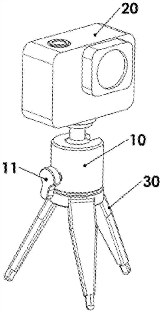
[0048] figure 1 A compact camera 20 is shown mounted on a positionable ball head 10 with a positioning clamp lever 11 . The positionable ball head 10 is mounted on a compact tripod 30 .
[0049] In order to allow an ergonomic shape and size of the positioning clamp bar 11 without detrimentally increasing the height of the positionable ball head 10 , the positioning clamp bar 11 protrudes below the base of the positionable ball head 10 .
[0050] It should be noted that the compact tripod 30 lacks the weight and footprint necessary to ensure stability under conditions of vibration and motion.
...
PUM
 Abstract
Description
Claims
Application Information
 - R&D Engineer
- R&D Manager
- IP Professional
- Industry Leading Data Capabilities
- Powerful AI technology
- Patent DNA Extraction
Browse by: Latest US Patents, China's latest patents, Technical Efficacy Thesaurus, Application Domain, Technology Topic, Popular Technical Reports.
© 2024 PatSnap. All rights reserved.Legal|Privacy policy|Modern Slavery Act Transparency Statement|Sitemap|About US| Contact US: help@patsnap.com