Locking mechanism of rotating piece and steel rail grinding device containing same

A technology of rotating parts and locking, which is used in tracks, track laying, track maintenance, etc., can solve the problems of increasing the complexity of the overall mechanism, limited mechanism space, locking failure, etc., and achieves safe, effective and normal operation and small motion friction coefficient. , The effect of not easy to slip off

Inactive Publication Date: 2019-12-24
CHINA RAILWAYS CORPORATION +1
View PDF0 Cites 0 Cited by
  • Summary
  • Abstract
  • Description
  • Claims
  • Application Information

AI Technical Summary

Problems solved by technology

However, the conventional locking method is applied in a special environment, for example, when it is applied in the railway industry, due to the long-term and large amount of vibration during the operation of the vehicle, it is easy to cause the locking failure
[0008] 2. The redundancy is not high. Once a set of locking methods fails, the overall locking will fail
As in Scheme 2, although multiple sets of locking mechanisms can be arranged (multiple sets of pins are fixedly installed on the circumference of the rotating part), due to the limited space of the mechanism, the number of locking mechanisms is small, and it will also increase the complexity of the overall mechanism. Daily maintenance It is more inconvenient, and correspondingly increases the cost of use
[0009] 3. Option 1 and Option 3 rely on friction locking. The disadvantage is that when it is applied in an environment with a large amount of vibration, the locking mechanism may be slightly shifted, which will cause the locking to fail.
In addition, in Scheme 2, the pins are used to lock the rotating parts axially or radially. At this time, the pins are subjected to shear force. Under a large amount of vibration environment, the pins and pin holes will be squeezed or even torn, causing the pins and pin holes to be damaged. The gap between the mating surfaces increases, and the lock fails

Method used


Image

  • Locking mechanism of rotating piece and steel rail grinding device containing same
  • Locking mechanism of rotating piece and steel rail grinding device containing same
  • Locking mechanism of rotating piece and steel rail grinding device containing same

Examples


Embodiment 1

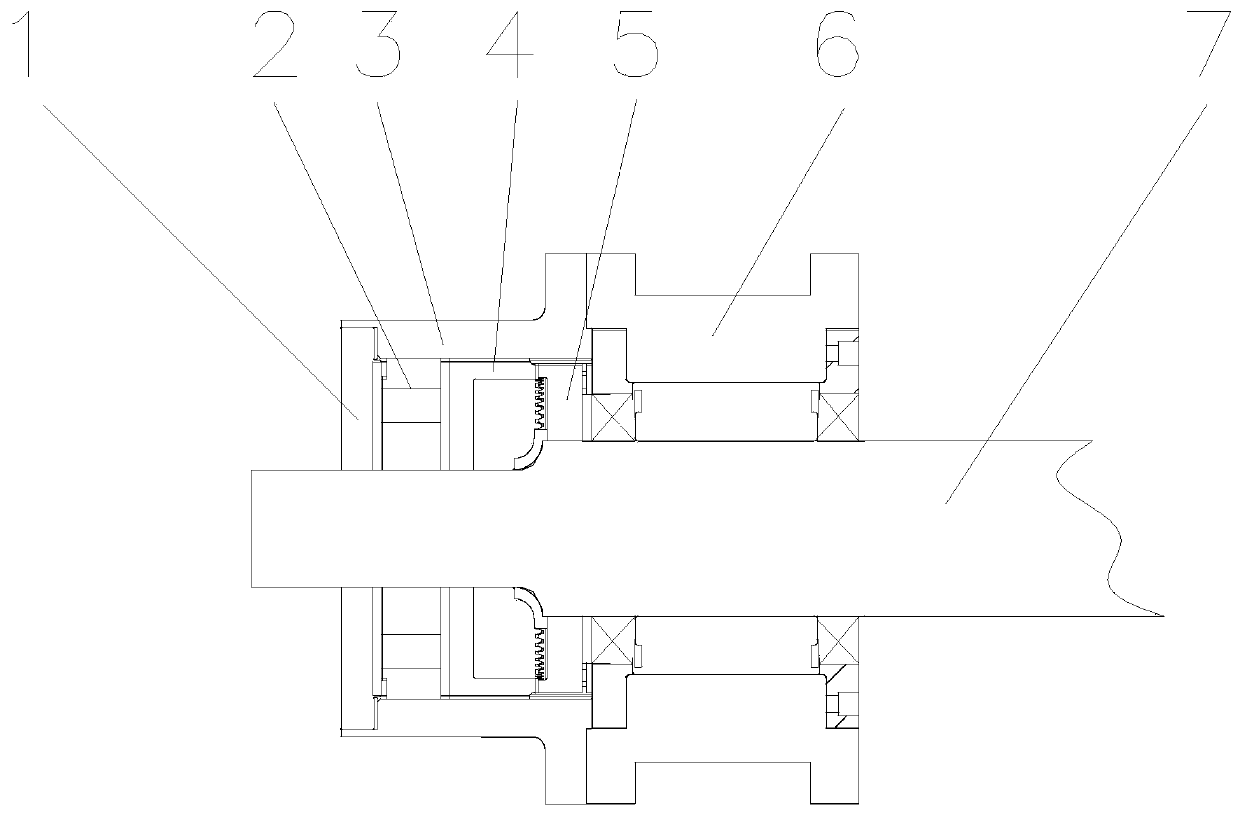
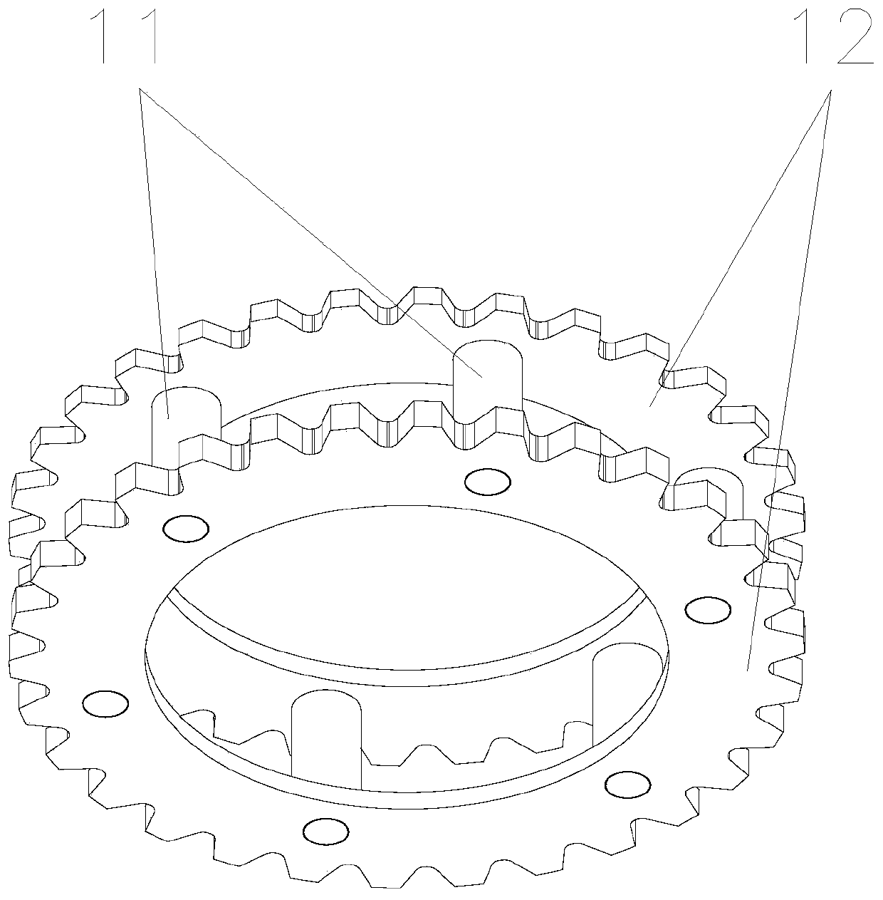
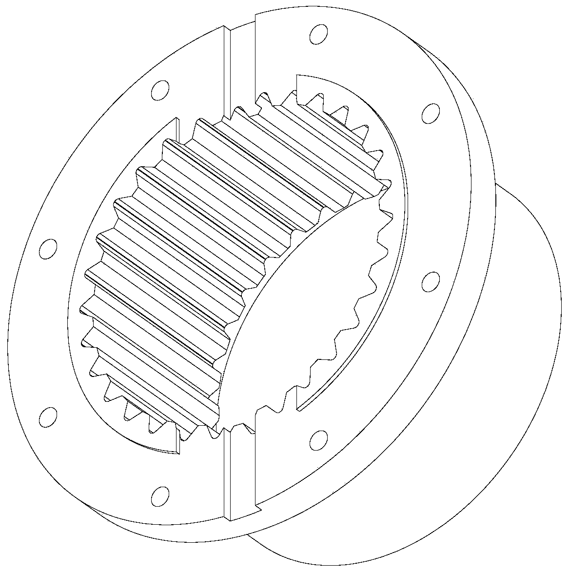
[0040] The present invention provides a locking mechanism for the rotating part 7, the rotating part 7 is coaxially pierced with a fixed locking cylinder 3, and there is formed between the inner wall of the locking cylinder 3 and the outer surface of the rotating part 7 An annular gap; the annular gap is provided with a chainring set that is meshed and connected under the action of a pre-tightening force; the toothed set includes a movable toothed plate 4 that can move in the annular gap, and the middle part of the movable toothed plate 4 is open. There is an avoidance hole and slides through the rotating part 7, and the fixed toothed plate 5 is fixedly sleeved on the rotating part 7. The movable toothed plate 4 and the fixed toothed plate 5 are connected by end teeth; the outer toothed plate 4 The round surface and the inner wall of the locking cylinder 3 are connected by a key that limits the rotation of the movable toothed disc 4 .

[0041] As for the face teeth, many small...

Embodiment 2

[0057] A rail grinding device, including the locking mechanism of the rotating part 7 described in any one of the above technical solutions; the other end of the rotating part 7 is fixedly connected to the rotating part support seat 6, and the rotating part 7 is fixedly connected with Grinding the fixing frame 8, the grinding unit 9 arranged in multiple rows is fixed on the outer periphery of the grinding fixing frame 8.

[0058] There are two groups of rail grinding devices corresponding to the width of the rail on the rail, and a frame body 10 is fixedly connected between the two groups of rail grinding devices.

[0059] When this rail grinding device works, it advances along the length direction of the rail, and there are defects such as cracks or other pits on the top surface of the rail (the surface where the rail is combined with the train roller), which needs to be polished and maintained. During the advance of the rail grinding device, one row of grinding units 9 is ti...


PUM


Abstract

The invention relates to the technical field of locking mechanisms, and discloses a locking mechanism of a rotating piece. A fixed locking cylinder is coaxially penetrated outside the rotating piece,and an annular gap is formed between the inner wall of the locking cylinder and the outer circumferential surface of the rotating piece; the annular gap is internally provided with a tooth disc groupwhich is meshed and connected under the action of a pretightening force; the tooth disc group comprises a movable tooth disc which can move in the annular gap, wherein an avoidance hole is formed in the middle part of the movable tooth disc and is slidably penetrated on the rotating piece, and a fixed tooth disc fixedly sleeving on the rotating piece, and the movable tooth disc and the fixed toothdisc are connected through end face teeth; and the outer circumferential surface of the movable tooth disc is connected with the inner wall of the locking cylinder by a key which limits the rotationof the movable tooth disc. The invention also discloses a rail grinding device containing the locking mechanism, wherein a grinding fixing frame is fixedly connected to the rotating piece, and a plurality of grinding units arranged in rows are fixedly arranged on the periphery of the grinding fixing frame. The locking mechanism of the rotating piece applies a continuous acting force when the end face teeth are meshed to press the meshing part, and lock the rotating piece to prevent the rotating part from rotating freely.

Description

technical field [0001] The invention relates to the technical field of locking mechanisms, in particular to a locking mechanism of a rotating part and a rail grinding device containing the locking mechanism. Background technique [0002] The commonly used rotation locking methods for rotating parts (rotating shafts) mainly include the following types: [0003] 1. The motor with brake locks the rotating parts. [0004] 2. Lock the rotating parts axially or radially with pins. [0005] 3. Self-locking through friction angle to achieve locking effect, such as worm gear-worm connection, locking the worm. [0006] The above rotation lock methods have some disadvantages: [0007] 1. Conventional deadlock is generally used in a relatively static environment, so there will be no major problems. However, the conventional locking method is applied in a special environment, for example, when it is applied in the railway industry, because there is a long-term and a large amount of v...

Claims


Application Information

Patent Timeline
Patent Type & Authority Applications(China)
IPC IPC(8): E01B31/17
CPCE01B31/17
Inventor 赵国堂王鹏翔王衡禹程广慧
Owner CHINA RAILWAYS CORPORATION
Why Eureka
Try Eureka