
A Wind-Induced Vibration Piezoelectric Energy Harvester

A piezoelectric energy harvesting and wind-induced technology, applied in piezoelectric effect/electrostrictive or magnetostrictive motors, electrical components, generators/motors, etc., which can solve the adjustment range of piezoelectric vibrator scale and system natural frequency Small, small effective wind speed range, lack of shape limiting measures and other problems, to achieve the effect of improving response characteristics and power generation capacity, controllable deformation, and high reliability

Active Publication Date: 2021-11-12
ZHEJIANG NORMAL UNIVERSITY
View PDF5 Cites 0 Cited by
  • Summary
  • Abstract
  • Description
  • Claims
  • Application Information

AI Technical Summary

Problems solved by technology

The common feature of the above-mentioned piezoelectric energy harvesters is to directly use the inertial force of the end mass of the piezoelectric vibrator to make it bend and deform and generate electricity. The main disadvantages are: poor wind speed adaptability, small effective wind speed range, bidirectional deformation of the piezoelectric vibrator, The sheet is subjected to alternating tensile and compressive stresses and lacks necessary shape-constraining measures, and the adjustable range of the piezoelectric vibrator scale and the natural frequency of the system is small

Method used


Image

  • A Wind-Induced Vibration Piezoelectric Energy Harvester
  • A Wind-Induced Vibration Piezoelectric Energy Harvester
  • A Wind-Induced Vibration Piezoelectric Energy Harvester

Examples


Embodiment Construction

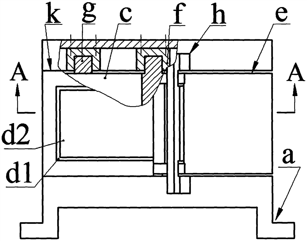
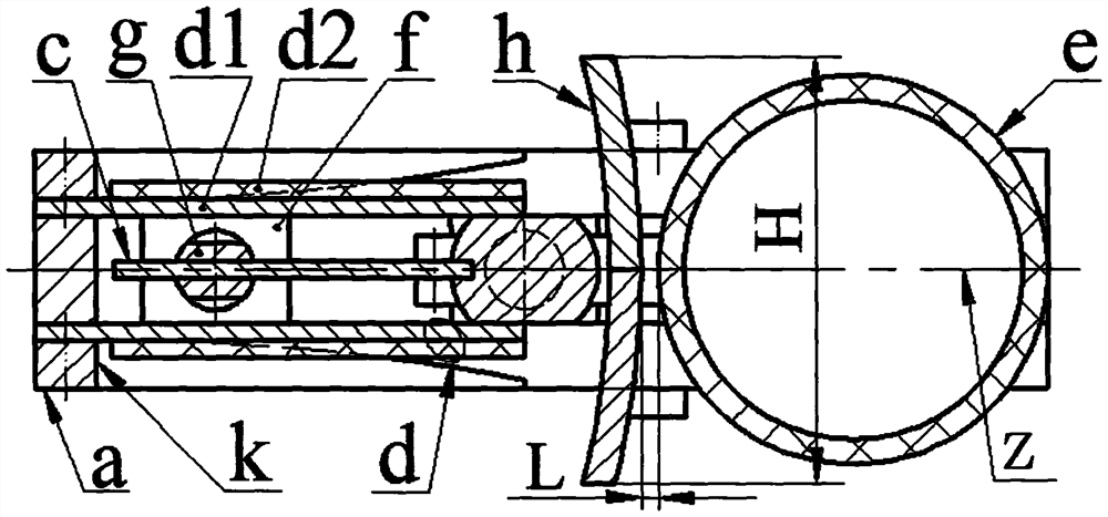
[0020] The upper and lower ends of the beam a3 of the bracket a are respectively provided with an upper beam a1 and a lower beam a2, the upper beam a1 and the lower beam a2 are parallel and symmetrically arranged on the upper and lower sides of the beam a3, and the upper beam a1 and the lower beam a2 are perpendicular to the beam a3 , the inner walls of the upper beam a1 and the lower beam a2 are provided with slides a4, and the two ends of the lower beam a2 are provided with feet a5: the upper and lower ends of the blunt body e1 of the coupler e are provided with ear plates e2, and the blunt body e1 is Hollow shell, the inner sides of the two lugs e2 are connected by a cylinder e3, and the outer sides of the two lugs e2 are provided with a semi-axis e4, the semi-axis e4 is coaxial with the cylinder e3 and its axis line is the axis of the blunt body e1 Parallel, there are two column planes e5 parallel to each other on the cylinder e3, and there are interconnected through groove...


PUM


Abstract

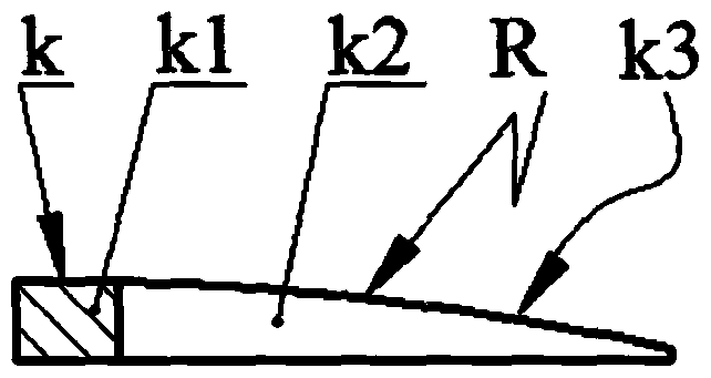
The invention relates to a wind-induced vibration piezoelectric energy harvester, which belongs to the technical field of new energy sources. The upper and lower ends of the beam of the bracket are respectively provided with upper and lower beams with slideways; the upper and lower ends of the blunt body of the coupler are provided with ear plates, the inner sides of the two ear plates are connected by cylinders, and the outer sides are equipped with half shafts. There are two parallel column planes, and the cylinder and the two ear plates are provided with interconnected through grooves; the two ends of the cylindrical pin and the two semi-axes are sleeved in the slideways of the upper and lower beams; one end of the reed It is placed in the through groove and fixed on the ear plate by screws, and the other end passes through the narrow slit of the cylindrical pin; the connecting ears of the two baffles are respectively installed on the upper and lower beams through screws, and the arc plates pass through the blunt body and the cylinder. The gap between the bodies passes through and contacts each other; one end of the piezoelectric vibrator composed of the substrate and the piezoelectric sheet is installed on the beam through the screw and the pressure plate of the shape-limiting frame, and the free end leans against the column plane; the two ends of the pressure plate of the shape-limiting frame Both are provided with a shape-limiting block with a shape-limiting surface, and the substrate at the fixed end of the piezoelectric vibrator is in contact with the shape-limiting surface.

Description

technical field [0001] The invention belongs to the technical field of new energy, and in particular relates to a wind-induced vibration piezoelectric energy harvester. Background technique [0002] In recent years, with the maturity of wireless sensor network technology and its popularization in the fields of environmental monitoring, health monitoring of large buildings and bridges, industry, military and public safety, micro-wind power that provides continuous energy supply The research on energy harvesters has attracted extensive attention from scholars at home and abroad. The miniature wind energy harvesters that have been proposed so far are basically based on electromagnetic principles and piezoelectric principles. Because piezoelectric energy harvesters do not generate electromagnetic interference during the power generation process, they are more suitable for wireless systems such as wireless network nodes. There are two main types of wind energy harvesters constru...

Claims


Application Information

Patent Timeline
Patent Type & Authority Patents(China)
IPC IPC(8): H02N2/18
CPCH02N2/186
Inventor 张忠华林仕杰罗素清吴鸣张昱任泽峰程光明
Owner ZHEJIANG NORMAL UNIVERSITY
Learn More