Positioning seat lifting mechanism

A lifting mechanism and positioning seat technology, which is applied in metal processing, metal processing equipment, manufacturing tools, etc., can solve the problems of insufficient space height under the table and insufficient installation of lifting cylinders, etc.

Pending Publication Date: 2020-03-27
HENGDIAN GRP INNUOVO ELECTRIC
View PDF0 Cites 3 Cited by
  • Summary
  • Abstract
  • Description
  • Claims
  • Application Information

AI Technical Summary

Problems solved by technology

For this reason, the positioning seat belonging to component A needs to be fixed on the lifting plate, and the positioning seat can be moved up and down through the lifting cylinder, but the space under the table is not high enough to install the lifting cylinder

Method used


Image

  • Positioning seat lifting mechanism
  • Positioning seat lifting mechanism

Examples


Embodiment Construction

[0014] The present invention will be further described below according to the accompanying drawings and specific embodiments.

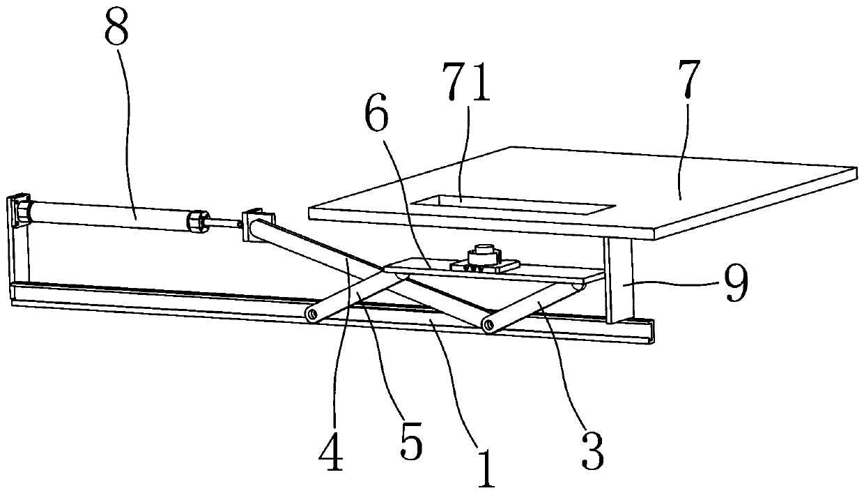
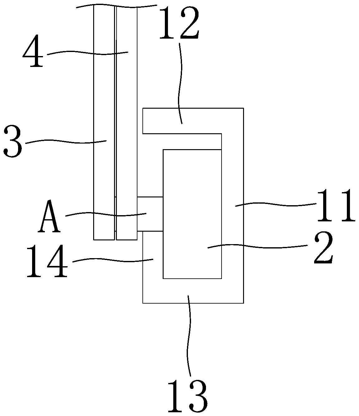
[0015] Depend on figure 1 , figure 2 As shown, a positioning seat lifting mechanism of the present invention includes a guide rail 1 arranged along the front and rear directions, a front sliding block 2 and a rear sliding block are slidably fixed on the guide rail 1, and the front sliding block 2 and the lower end of the first support plate 3 and push The lower end of the plate 4 is hinged and fixed, the rear sliding block is hinged and fixed with the lower end of the second support plate 5, the upper end of the first support plate 3 and the upper end of the second support plate 5 are respectively hinged and fixed with the front and rear ends of the lifting plate 6, and the upper end of the first support plate 3 is located at The front side of the lower end of the first support plate 3, the upper end of the second support plate 5 is located at the f...


PUM


Abstract

The invention aims to provide a positioning seat lifting mechanism which can be used for insufficient height space below a tabletop. To achieve the purpose, according to the technical scheme of the positioning seat lifting mechanism, the positioning seat lifting mechanism comprises a guide rail arranged in the front-back direction; a front sliding block and a rear sliding block are slidably fixedto the guide rail; the front sliding block is hinged to the lower end of a first supporting plate and the lower end of a pushing plate; the rear sliding block is hinged and fixed to the lower end of the second supporting plate; and the upper end of the first supporting plate and the upper end of the second supporting plate are hinged and fixed to the front end and the rear end of a lifting plate correspondingly. The tabletop and a telescopic mechanism are arranged above the guide rail. The tabletop is provided with an avoiding groove penetrating up and down. The output end of the telescopic mechanism is hinged to the upper end of the pushing plate. The upper end of the pushing plate is located on the rear side of the lower end of the pushing plate. A vertically arranged guide plate is arranged on the lower side of the tabletop and is located on the front side of the lifting plate.

Description

technical field [0001] The invention relates to an automatic assembly equipment, in particular to a positioning seat lifting mechanism. Background technique [0002] In order to save factory space, reduce the number of equipment and reduce production costs, some components with similar assembly steps can share one equipment. For example, component A needs to be loaded and assembled with three kinds of components, component B needs to be loaded and assembled with two kinds of components, the components used in component B can be used for the assembly of component A, and the assembly of component A Three positioning seats are required in the process, and two positioning seats are required in the assembly process of component B. Existing automated assembly equipment usually uses jaw components for mobile loading. During the assembly process of component B, the positioning seat that belongs to component A will be on the path of the jaw component. For this reason, the positioni...

Claims


Application Information

Patent Timeline
Patent Type & Authority Applications(China)
IPC IPC(8): B23P19/00
CPCB23P19/00
Inventor 王辉钱豪
Owner HENGDIAN GRP INNUOVO ELECTRIC
Why Eureka
Try Eureka