A water transfer printing machine for automotive interior parts
A technology for automotive interior parts and transfer printing machines, which is applied in the direction of rotary printing machines, printing machines, transfer printing, etc., can solve the problems of contact with water transfer printing molds, troubles, and affect the quality of automotive interior parts, etc., to achieve Facilitate the effect of water transfer printing
- Summary
- Abstract
- Description
- Claims
- Application Information
AI Technical Summary
Problems solved by technology
Method used
Image

Examples
Embodiment 1
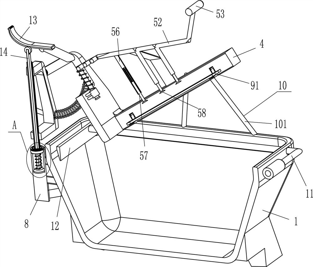
[0021] refer to Figure 1-Figure 4 , a water transfer machine for automotive interior parts, including a frame body 1, a bracket 2, a hollow shaft 3, a special-shaped plate 4, a fixing mechanism 5, an arc rod 6, a third spring 7, a hollow sleeve 8 and a limit Mechanism 9, a hollow sleeve 8 is fixedly connected to the middle part of the outer left side of the frame body 1, and a hollow shaft 3 is rotatably connected between the upper part of the inner side of the hollow sleeve 8, and a bracket 2 is fixedly connected to the upper part of the hollow shaft 3, and the front and rear sides of the bracket 2 A special-shaped plate 4 is hinged between the tops of the two sides, and the left side of the special-shaped plate 4 is provided with a fixing mechanism 5 that can absorb the automotive interior parts. 5 fit, the front and rear sides of the bracket 2 are slidingly provided with an arc rod 6, the right end of the arc rod 6 is fixedly connected to the outer left side of the special...
Embodiment 2
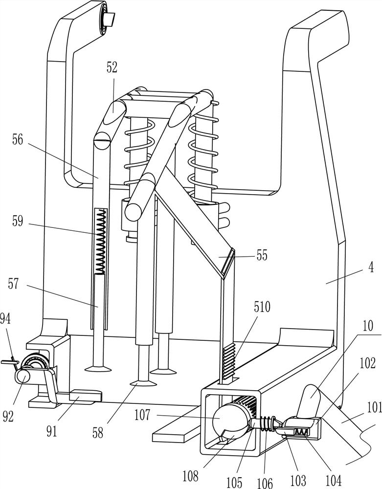
[0028] refer to Figure 1-Figure 4 Compared with Embodiment 1, the main difference of this embodiment is that this embodiment also includes a clamping mechanism 10, and the clamping mechanism 10 includes a support rod 101, a second sleeve 102, a block 103, and a fourth spring 104 , sliding bar 105, fifth spring 106 and circular block 107, two support rods 101 are fixedly connected to the top right side of the front and rear sides of the frame body 1, and a second set of support rods 101 is fixedly connected between the inner ends of the support rods 101 on each side. The cylinder 102, the second sleeve 102 is slidingly provided with a block 103, the fourth spring 104 is connected between the outer end of the block 103 and the inner wall of the second sleeve 102, and the right parts of the front and rear sides of the special-shaped plate 4 slide The type is provided with a sliding lever 105, the outer end of the sliding lever 105 contacts and cooperates with the block 103, and ...
Embodiment 3
[0031] refer to figure 1 , figure 2 and Figure 5 Compared with Embodiment 1 and Embodiment 2, the main difference of this embodiment is that in this embodiment, an n-type tie rod 11 and a scraper 12 are also included, and the upper right side of the frame body 1 is slidingly provided with an n-type tie rod 11, A scraper 12 is fixedly connected between the left ends of the n-type pull rods 11 .
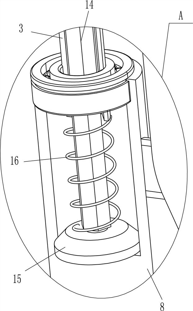
[0032] It also includes an arc-shaped plate 13, a hexagonal rod 14, an annular friction block 15 and a sixth spring 16. The hollow shaft 3 is slidingly provided with a hexagonal rod 14, and the bottom end of the hexalism rod 14 is fixedly connected with an annular friction block 15. , the annular friction block 15 is in contact with the inner bottom of the hollow sleeve 8, the sixth spring 16 is connected between the top of the annular friction block 15 and the bottom of the hollow shaft 3, and the sixth spring 16 is set on the hexagonal rod 14, and the special-shaped plate 4 is le...
PUM
 Abstract
Description
Claims
Application Information
 - R&D Engineer
- R&D Manager
- IP Professional
- Industry Leading Data Capabilities
- Powerful AI technology
- Patent DNA Extraction
Browse by: Latest US Patents, China's latest patents, Technical Efficacy Thesaurus, Application Domain, Technology Topic.
© 2024 PatSnap. All rights reserved.Legal|Privacy policy|Modern Slavery Act Transparency Statement|Sitemap