A solid wood water transfer printing and graining device for making furniture

A technology of water transfer printing and solid wood, applied in transfer printing, rotary printing machine, printing, etc., can solve the problems of low work efficiency and labor, and achieve the effect of high work efficiency

Active Publication Date: 2022-04-05
上海武驹实业有限公司
View PDF9 Cites 0 Cited by
  • Summary
  • Abstract
  • Description
  • Claims
  • Application Information

AI Technical Summary

Problems solved by technology

[0004] In order to overcome the shortcomings of manual water transfer printing on solid wood, which requires shaking and labor, and only one solid wood can be water transfer printing at a time, and the work efficiency is low, the technical problem of the present invention is to provide a It is more convenient for people to carry out water transfer printing on solid wood, which is labor-saving, and can carry out water transfer printing on multiple solid woods at the same time, which is a solid wood water transfer printing and graining device for furniture with high work efficiency.

Method used


Image

  • A solid wood water transfer printing and graining device for making furniture
  • A solid wood water transfer printing and graining device for making furniture
  • A solid wood water transfer printing and graining device for making furniture

Examples


Embodiment 1

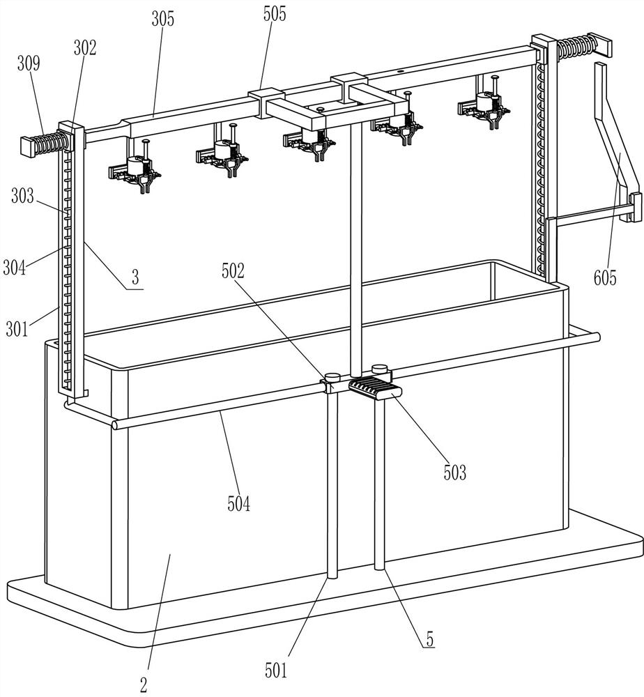
[0023] see Figure 1-Figure 4 , a solid wood water transfer printing device for making furniture, including a bottom plate 1, a frame body 2, a moving component 3 and a clamping component 4, a frame body 2 is installed in the middle of the top rear side of the bottom plate 1, and the outer side of the frame body 2 A moving assembly 3 is arranged between the left and right sides, and clamping assemblies 4 are evenly spaced on the moving assembly 3 .

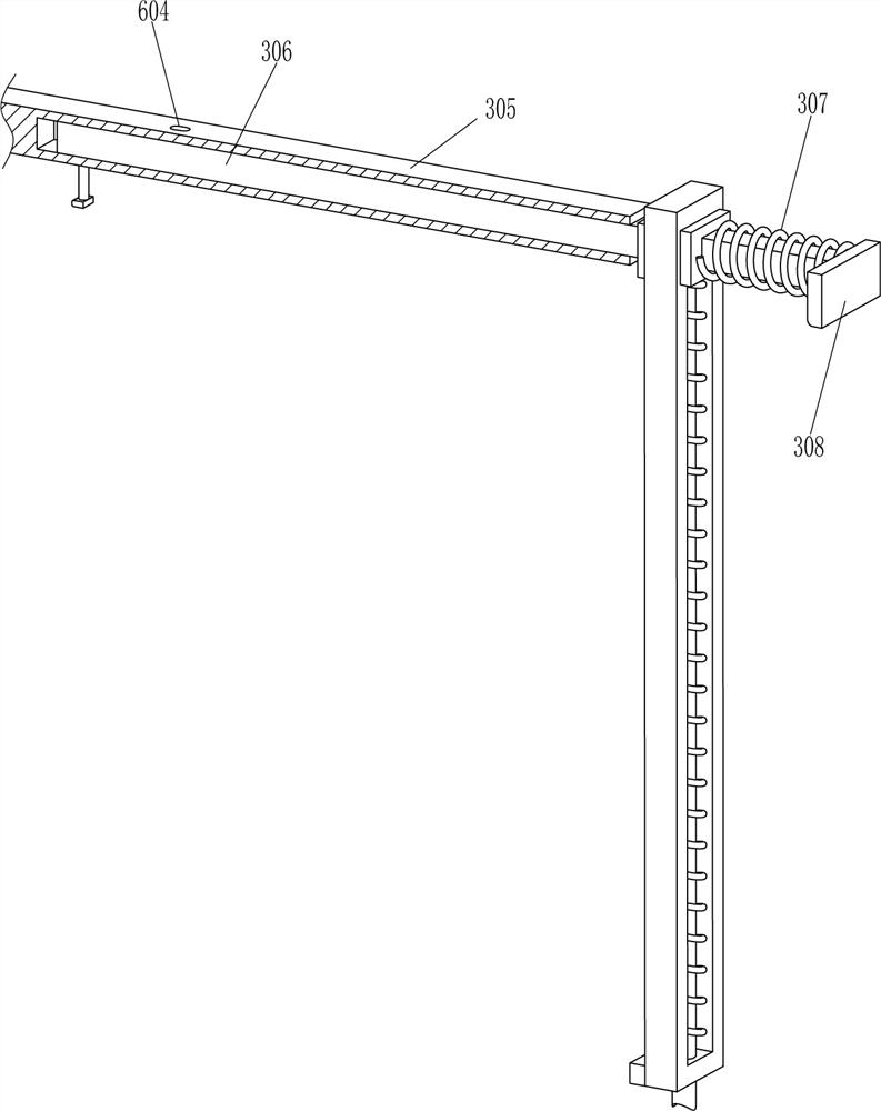
[0024] The mobile assembly 3 includes a guide frame 301, a first slider 302, a guide rod 303, a first spring 304, a mounting rod 305, a first slide rod 306, a second spring 307, a contact block 308 and a third spring 309, and the frame body 2. A guide frame 301 is fixedly connected to the upper parts of the outer left and right sides. The guide frame 301 is slidably provided with a first slide block 302. The guide rod 303 is connected with a guide rod 303 slidingly in the middle of the bottom of the guide frame 301. The top end of...

Embodiment 2

[0030] see figure 1 and figure 2 Compared with Embodiment 1, the main difference of this embodiment is that in this embodiment, a pedal assembly 5 is also included, and the pedal assembly 5 includes a second slide bar 501, a second slide block 502, a pedal 503, and a connecting frame 504 and the guide sleeve 505, two second sliding rods 501 are fixedly connected to the middle front side of the top of the bottom plate 1, and a second sliding block 502 is provided slidingly between the two second sliding rods 501, and the left and right sides of the second sliding block 502 All are fixedly connected with a connecting frame 504, the rear side of the top of the connecting frame 504 is fixedly connected with the bottom end of the guide rod 303, the middle part of the front side of the second slider 502 is fixedly connected with a pedal 503, and a sliding guide sleeve 505 is provided on the mounting rod 305. The middle of the top of the second sliding block 502 is fixedly connecte...

Embodiment 3

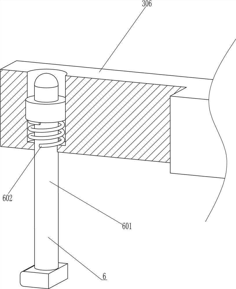
[0033] see figure 1 , figure 2 , Figure 4 , Figure 5 and Figure 6 Compared with Embodiment 1 and Embodiment 2, the main difference of this embodiment is that in this embodiment, a shaking assembly 6 is also included. The left part of the first sliding bar 306 is slidingly provided with a locking bar 601, a sixth spring 602 is wound between the upper part of the locking bar 601 and the inside of the first sliding bar 306, and the bottom end of the locking bar 601 runs through the mounting bar 305 to slide and cooperate with it. , the bottom right side of the right guide sleeve 505 is affixed with a wedge-shaped block 603, the wedge-shaped block 603 cooperates with the clamping rod 601, and the front part of the right side of the top of the frame body 2 is affixed with a special-shaped rod 605, and the special-shaped rod 605 cooperates with the contact block 308. A through hole 604 is opened on the right side of the top of the rod 305 , and the through hole 604 cooperate...


PUM


Abstract

The invention relates to a graining device, in particular to a solid wood water transfer printing graining device for making furniture. The technical problem is how to design a solid wood water transfer printing device for making furniture that is more convenient for people to carry out water transfer printing on solid wood, which is more labor-saving, and can carry out water transfer printing on multiple solid woods at the same time, and has high work efficiency. . A solid wood water transfer printing and graining device for making furniture, comprising a bottom plate, a frame body is fixedly connected to one side of the bottom plate; a moving component is installed between the outer two sides of the frame away from the bottom plate, and is used to make the solid wood Movement; a clamping component, installed on the moving component, used for clamping solid wood. In the present invention, the solid wood is inserted into the sleeve and clamped and fixed by the clamp block, and the installation rod is pushed to drive the solid wood to move down to the frame, so that the water transfer printing process can be completed, so that the wood grain is printed on the solid wood. Multi-root solid wood is processed by water transfer printing, and the work efficiency is high.

Description

technical field [0001] The invention relates to a graining device, in particular to a solid wood water transfer printing graining device for making furniture. Background technique [0002] Furniture refers to the category of utensils and facilities necessary for human beings to maintain normal life, engage in production practice and carry out social activities. Furniture also follows the footsteps of the times and continues to develop and innovate. Up to now, there are many categories, different materials, complete varieties, and different uses. It is an important basis for establishing a working and living space. In furniture production, solid wood must be used, but in order to make the furniture more beautiful, water transfer printing will be performed on the solid wood to make the wood grain printed on the solid wood. [0003] At present, most of the water transfer printing on solid wood is done manually. First, people need to hold the solid wood and move it into the wat...

Claims


Application Information

Patent Timeline
Patent Type & Authority Patents(China)
IPC IPC(8): B41F16/00
CPCB41F16/00
Inventor 陈淑华
Owner 上海武驹实业有限公司
Why Eureka
Try Eureka