Unlock instant, AI-driven research and patent intelligence for your innovation.

Voice coil and winding method thereof and loudspeaker with voice coil

A wire-winding method and coil-winding technology, applied to sensors, electrical components, etc., can solve problems such as voice coil collision, and achieve the effect of improving the quality of pure sound

Inactive Publication Date: 2020-04-24
AAC TECH PTE LTD
View PDF7 Cites 2 Cited by
  • Summary
  • Abstract
  • Description
  • Claims
  • Application Information

AI Technical Summary

Problems solved by technology

[0005] The purpose of the present invention is to provide a voice coil, a voice coil winding method and a speaker with the voice coil, so as to solve the problem that the curved wire on the upper end surface of the voice coil collides with the voice coil during the vibration process of the voice coil

Method used


Image

  • Voice coil and winding method thereof and loudspeaker with voice coil
  • Voice coil and winding method thereof and loudspeaker with voice coil
  • Voice coil and winding method thereof and loudspeaker with voice coil

Examples


Embodiment Construction

[0026] The present invention will be further described below in conjunction with the accompanying drawings and embodiments.

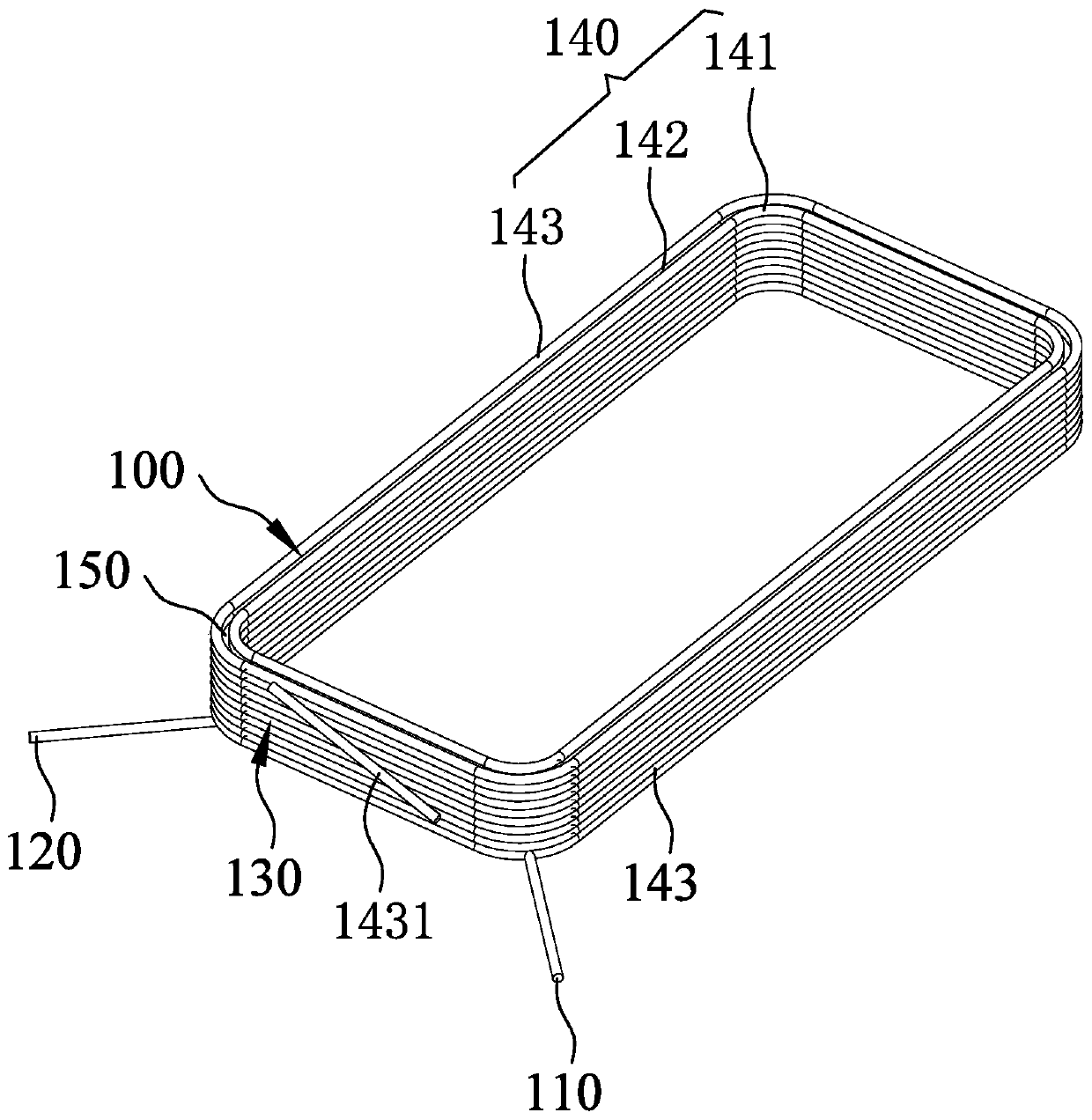
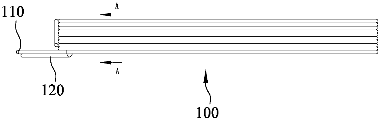
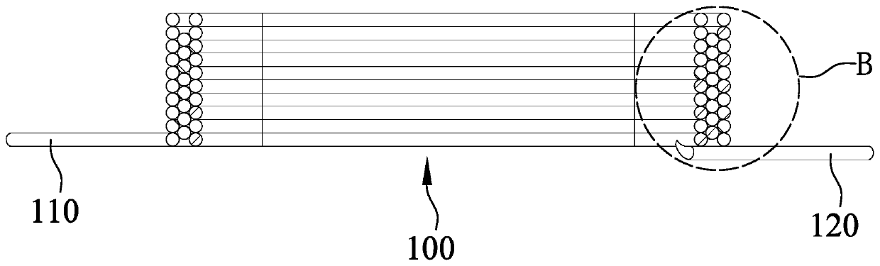
[0027] In order to solve the technical problem, the present invention provides a voice coil on the one hand. figure 1 It is a schematic diagram of an embodiment of the voice coil structure of the present invention, refer to figure 1 The voice coil 100 has a cubic structure as a whole. The voice coil 100 includes a voice coil input terminal 110, a voice coil output terminal 120, and a voice coil winding 130. The voice coil 100 is sequentially wound from the inside to the outside to form a three-layer coil structure 140. These are the first layer coil 141 , the second layer coil 142 , and the third layer coil 143 , and each layer of coil structure 140 is wound to form a multi-turn structure. A winding switching portion 150 is provided between two adjacent layers of coil structures. The winding switching portion 150 is a concave structure, and the winding...


PUM


Abstract

The invention provides a voice coil and a winding method thereof and a loudspeaker with the voice coil. A winding switching part is arranged between every two adjacent layers of coils, the two ends ofeach winding switching part are located at the top and the bottom of the voice coil respectively, one end of each winding switching part is connected with the wire outlet end of the inner side of thecorresponding two adjacent layers of coil structures, and the other end of each winding switching part is connected with the wire inlet end of the outer side of the corresponding two adjacent layersof coils; and the output end of the voice coil is obliquely pulled downwards from the top of the Nth layer of coil to the bottom of the (N-1)th layer of coil and is wound to the Nth layer along the bottom of the (N-1)th layer of coil, so that the output end of the voice coil and the input end of the voice coil are positioned on the same side of the voice coil. The wire outlet end of the Nth layerof coil of the voice coil is obliquely pulled to the bottom of the (N-1)th layer of coil and is wound to the Nth layer of coil along the bottom of the (N-1)th layer of coil, so that the voice coil ofwhich the voice coil output end and the voice coil input end are positioned on the same side of the voice coil, the voice coil winding method and the loudspeaker comprising the voice coil are formed.

Description

【Technical field】 [0001] The invention relates to the technical field of acoustic design, in particular to a voice coil and its winding method, and a loudspeaker with the voice coil. 【Background technique】 [0002] In the related art, the loudspeaker includes a pot frame and a vibration system and a magnetic circuit system accommodated in the pot frame. The vibration system includes a voice coil, and the voice coil includes a voice coil input end, a voice coil output end, and a voice coil winding wire. The winding wire is wound from the inner side of the voice coil to the outer side to form a multi-layer structure. [0003] In the loudspeaker with a magnetic circuit in the direction of the long axis and no magnetic circuit in the direction of the short axis, the voice coils are arranged in an odd number of layers, the incoming and outgoing lines are distributed on the upper and lower end faces of the voice coil, and the outgoing lines on the upper end face are bent downward....

Claims


Application Information

Patent Timeline
IPC IPC(8): H04R9/04H04R9/06
CPCH04R9/04H04R9/06
Inventor 蔡雪雷赵彬陈敏敏
Owner AAC TECH PTE LTD
Features
  • R&D
  • Intellectual Property
  • Life Sciences
  • Materials
  • Tech Scout
  • Unparalleled Data Quality
  • Higher Quality Content
  • 60% Fewer Hallucinations
Learn More