Light valve driving control method and device and projection equipment

A light valve and control signal technology, applied in the field of projection display, can solve problems such as light valve damage, mechanical fatigue of the driving device, and inability to distinguish colors

Active Publication Date: 2020-06-05
QINGDAO HISENSE LASER DISPLAY CO LTD
View PDF9 Cites 0 Cited by
  • Summary
  • Abstract
  • Description
  • Claims
  • Application Information

AI Technical Summary

Problems solved by technology

In the DLP projection equipment, the light source outputs the three primary color beams sequentially, and the time for outputting each primary color beam of the three primary colors (red, green, blue) is very short each time, so although the three primary colors enter the human body in different time periods Eyes, but due to the persistence of vision of the human eye, it is impossible to distinguish the colors that enter the human eye within such a subtle difference, so in terms of perception, it will form a colorful image
[0004] Since t

Method used


Image

  • Light valve driving control method and device and projection equipment
  • Light valve driving control method and device and projection equipment
  • Light valve driving control method and device and projection equipment

Examples


Embodiment 1

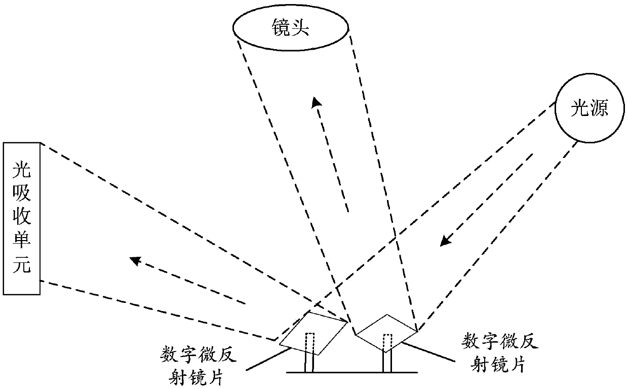
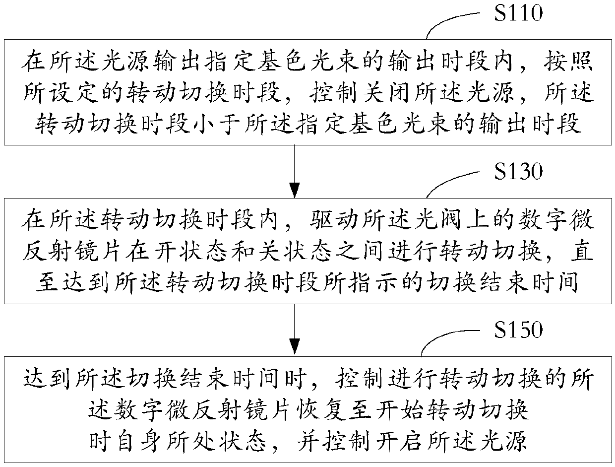
[0030] figure 2 It is a flow chart of a light valve driving control method shown according to an exemplary embodiment. Applied to a light valve composed of a number of digital micro-mirror mirrors, the digital micro-mirror mirrors reflect the primary color light beams sequentially output by the light source for projection display of color images, including:

[0031] Step S110, during the output period of the light source outputting the specified primary color light beam, control to turn off the light source according to the set rotation switching period, and the rotation switching period is shorter than the output period of the specified primary color light beam.

[0032] Step S130, within the rotation switching period, drive the digital micro-reflector on the light valve to switch between the on state and the off state until the switching end time indicated by the rotation switching period is reached.

[0033] Step S150 , when the switching end time is reached, control the ...

Embodiment 2

[0046] In one embodiment, the designated primary color light beam is a blue light beam. Compared with red and green, the human eye has the least sensitivity to blue, and blue contributes the least to the brightness of the displayed image. Therefore, the rotation switching period is configured within the output period of the light source outputting blue light beams, even when the rotation switching When the light source is turned off during the time period, the brightness of the projected and displayed image has little change, which cannot be distinguished by human eyes, thereby reducing the impact on the brightness of the projected and displayed image.

Embodiment 3

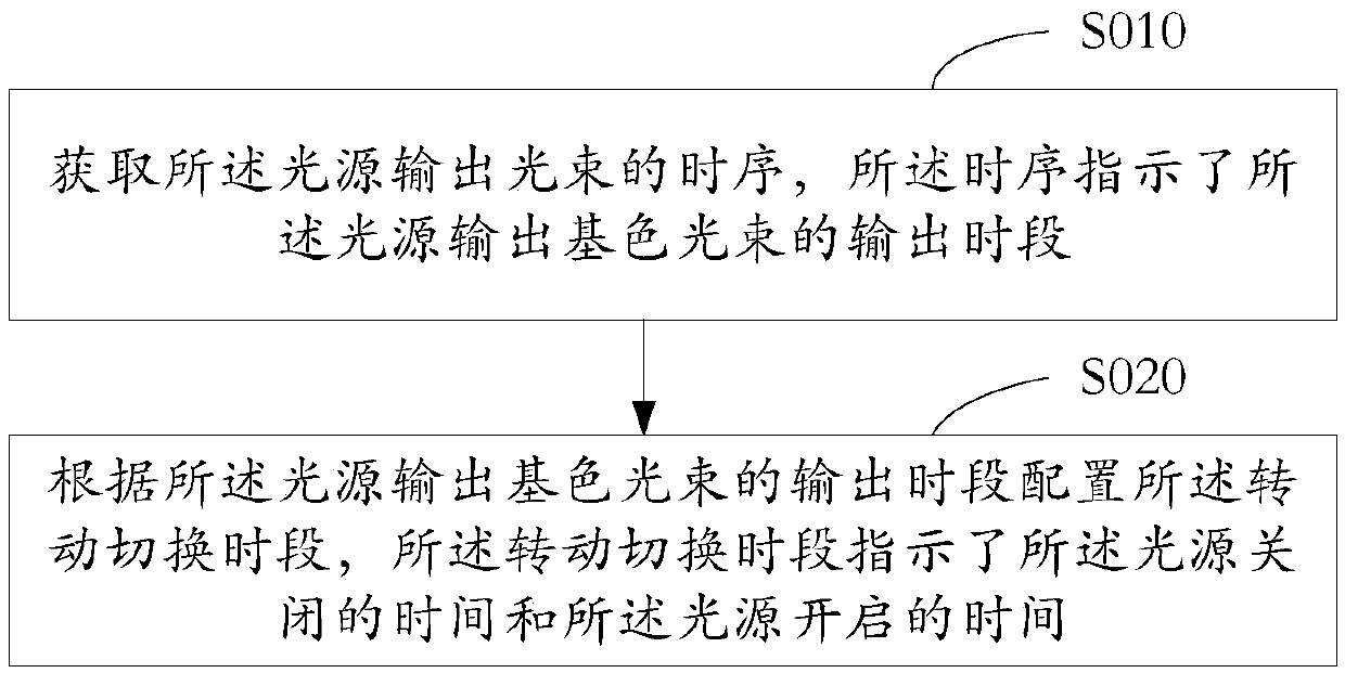
[0048] In one embodiment, as image 3 As shown, the method also includes:

[0049] Step S010, acquiring the time sequence of the light source outputting the light beams, the time sequence indicating the output period of the light source outputting the primary color light beams.

[0050] Step S030, configuring the rotation switching period according to the output period of the light source outputting the primary color light beam, and the rotation switching period indicates the time when the light source is turned off and the time when the light source is turned on.

[0051] Since the light source sequentially outputs red, green and blue beams, correspondingly, it has timings for outputting various primary color beams, for example, a timing sequence for blue beams. Correspondingly, the rotation switching period is configured according to the output period of the light source outputting the primary color light beam. Therefore, it is ensured that both the start time and the end ...


PUM


Abstract

The invention relates to the field of projection display, and particularly discloses a light valve driving control method and device. The method comprises the steps of: controlling to turn off a lightsource according to a set rotation switching time period in an output time period when the light source outputs a specified primary color light beam, and enabling the rotation switching time period to be smaller than the output time period of the specified primary color light beam, in the rotation switching time period, driving a digital micro-reflection lens on the light valve to perform rotation switching between an on state and an off state until the switching end time indicated by the rotation switching time period is reached, and when the switching end time is up, controlling the digitalmicro-reflection lens subjected to rotation switching to recover to the state where the digital micro-reflection lens is located when rotation switching is started, and controlling the light source to be turned on. By repeatedly reversing the digital micro-reflection lens in the rotation switching time period, the mechanical fatigue state caused by the fact that the digital micro-reflection lensis kept in the same state for a long time in the image display process can be relieved.

Description

technical field [0001] The present disclosure relates to the field of projection display, in particular to a light valve drive control method, device and projection equipment. Background technique [0002] DLP (Digital Light Processing, digital light processing) projection equipment is based on the light valve (also known as DMD, Digital Micro-mirror Device digital micro-mirror device) configured inside the light valve (also known as DMD, Digital Micro-mirror Device) to output the light source. The light beam is reflected, thereby performing the projection display of the image. On the light valve, each digital micro-mirror has its own independent driving device, which is used to support the rotation and switching of the digital micro-mirror between the on state and the off state, wherein the digital micro-mirror is between the on state and the off state. The switching speed can reach thousands of times per second. [0003] figure 1 is the working schematic diagram of the ...

Claims


Application Information

Patent Timeline
IPC IPC(8): G03B21/20
CPCG03B21/2066G09G3/34H04N9/3161H04N9/3164H04N9/3111H04N9/3158H04N9/312G03B21/2033G03B21/206G03B21/008H04N9/3114
Inventor 肖纪臣赵一石
Owner QINGDAO HISENSE LASER DISPLAY CO LTD
Why Eureka
Try Eureka