Air compressor

An air compressor and body technology, applied in the field of air compressors, can solve the problems of complicated oil circuit of the reversing valve, high cost, pressure pulsation, etc., to avoid electrical instability factors, save space and parts, and have a long working life. Effect

Inactive Publication Date: 2020-06-09
韩国昊
View PDF11 Cites 0 Cited by
  • Summary
  • Abstract
  • Description
  • Claims
  • Application Information

AI Technical Summary

Problems solved by technology

Although the double-plunger reciprocating air compressor can achieve continuous pressure output, the output pressure is zero at the moment of reversing, which makes the output pressure pulsate. It cannot be used in some occasions that require constant pressure. For example, the application number is: 201810479411.1. The hydraulically driven reciprocating air compressor needs to stop after the piston moves in place when it is working, and wait for the external reversing valve to change direction before moving in the reverse direction, which makes the output pressure pulsate, and the external reversing valve so Large size and high cost; the external reversing valve has complex oil circuit, complex control, and complex structure. When a fault occurs, it is not only difficult to troubleshoot the problem, but also inconvenient to maintain

Method used


Image

  • Air compressor
  • Air compressor
  • Air compressor

Examples


Embodiment Construction

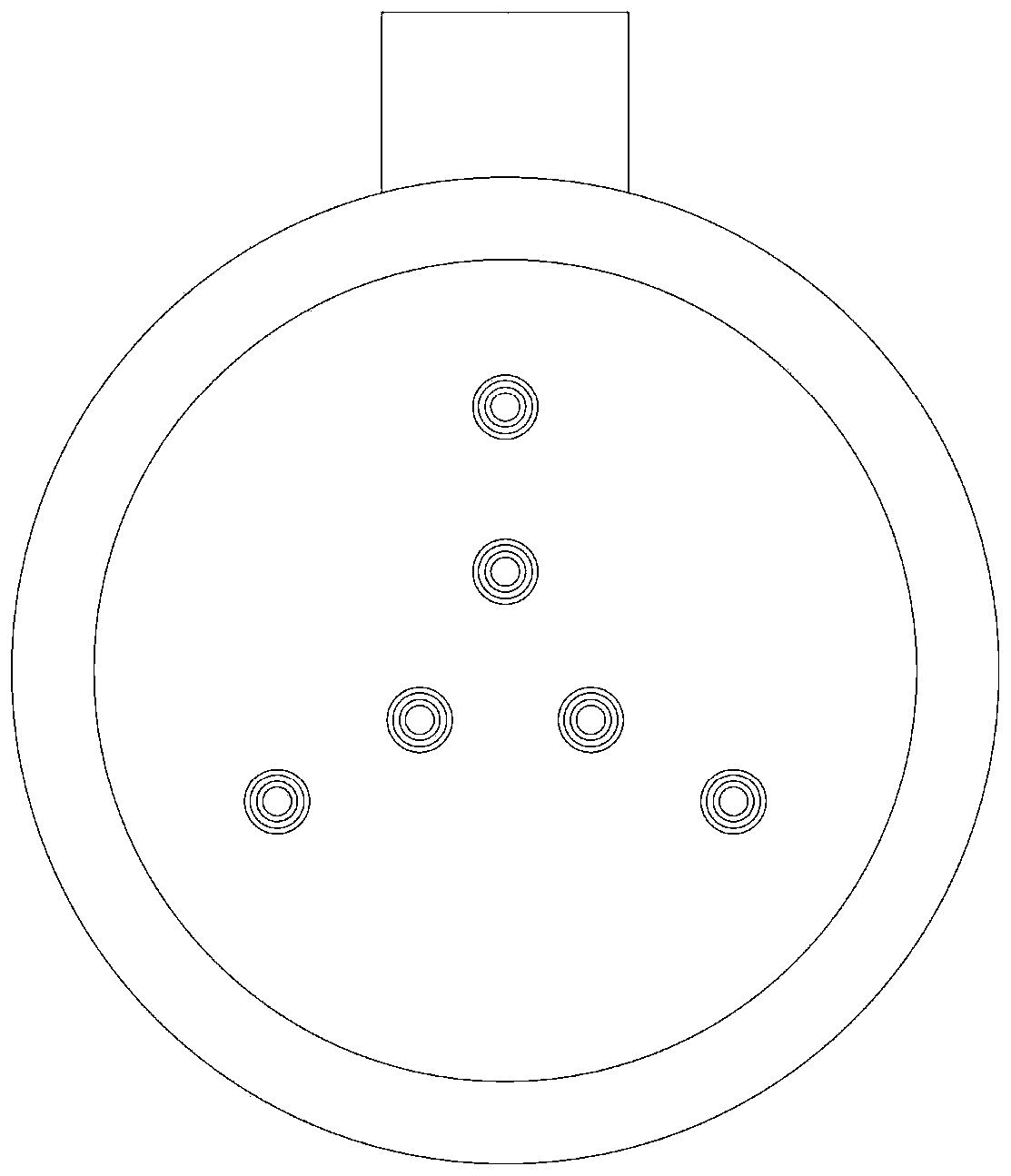
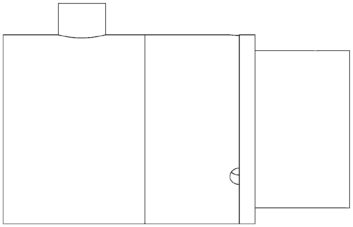
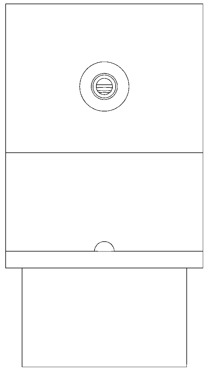
[0025] see Figure 1-13 As shown, an air compressor includes a body 1, and the first axial hole, the second axial hole, and the third axial hole opened at the left end are evenly arranged in the body 1 along the circumferential direction, and the body 1 The left end cover 6 is fixedly installed on the left side of 1, and the right casing 2 is fixedly installed on the right side; a right chamber 2a is formed between the body 1 and the right casing 2; a first piston is slidably connected in the first axial hole body 5a, the second piston body 5b is slidably connected in the second axial hole, and the third piston body 5c is slidably connected in the third axial hole; the right side of the first piston body 5a is extended with a The first piston rod 511 in 2a, the right side of the second piston body 5b are all extended with the second piston rod 512 that stretches into the right chamber 2a, the right side of the third piston body 5c is all extended with the second piston rod 512...


PUM


Abstract

The invention discloses an air compressor. The air compressor comprises a machine body, wherein at least three axial holes are formed in the machine body, a left end cover is fixedly arranged on the left side of the machine body, and a right machine shell is fixedly arranged on the right side of the machine body; a piston body is slidably connected in each axial hole, and the right side of each piston body is provided with a piston rod in an extending mode; pumping assemblies corresponding to the axial holes in one-to-one correspondence are arranged in the left end cover; the right side of themachine body is provided with a first concave spherical groove, and the right machine shell is provided with a second concave spherical groove; oil holes are formed in the machine body; the side surface of the right machine shell is provided with a P port and a T port; a rotating block is rotationally connected in the right machine shell, a rotating groove is formed in the left end of the rotating block in the direction perpendicular to the inclined plane, and a flow distribution shaft is rotationally connected in the rotating groove; and the lateral surface of the outer circumference of theflow distribution shaft is provided with a convex edge in the radial direction, and the right end of each piston rod is hinged to the convex edge through a ball. The air compressor has the advantagesthat the structure is compact, the overall design is highly integrated, a motor is not needed, electric instability factors are avoided, the air compressor can work for a long time, and the service life is long.

Description

technical field [0001] The invention belongs to the technical field of air compressors, and in particular relates to an air compressor. Background technique [0002] The reciprocating air compressors currently used in the market are mainly double-piston reciprocating air compressors. Although the double-plunger reciprocating air compressor can achieve continuous pressure output, the output pressure is zero at the moment of reversing, which makes the output pressure pulsate. It cannot be used in some occasions that require constant pressure. For example, the application number is: 201810479411.1. The hydraulically driven reciprocating air compressor needs to stop after the piston moves in place when it is working, and wait for the external reversing valve to change direction before moving in the reverse direction, which makes the output pressure pulsate, and the external reversing valve so The volume is large and the cost is high; the external reversing valve has complex oil...

Claims


Application Information

Patent Timeline
Patent Type & Authority Applications(China)
IPC IPC(8): F04B35/02F04B49/00F04B27/00F04B39/10
CPCF04B35/008F04B49/002F04B27/00F04B39/10
Inventor 韩国昊其他发明人请求不公开姓名
Owner 韩国昊
Why Eureka
Try Eureka