
Orthopedic traction device

A traction device and orthopedic technology, applied in passive exercise equipment, physical therapy, etc., can solve problems such as poor comfort, poor reliability, and movement, and achieve the effect of improving comfort and reliability

Inactive Publication Date: 2020-06-30
泰信利美信息科技(常州)有限公司
View PDF16 Cites 3 Cited by
  • Summary
  • Abstract
  • Description
  • Claims
  • Application Information

AI Technical Summary

Problems solved by technology

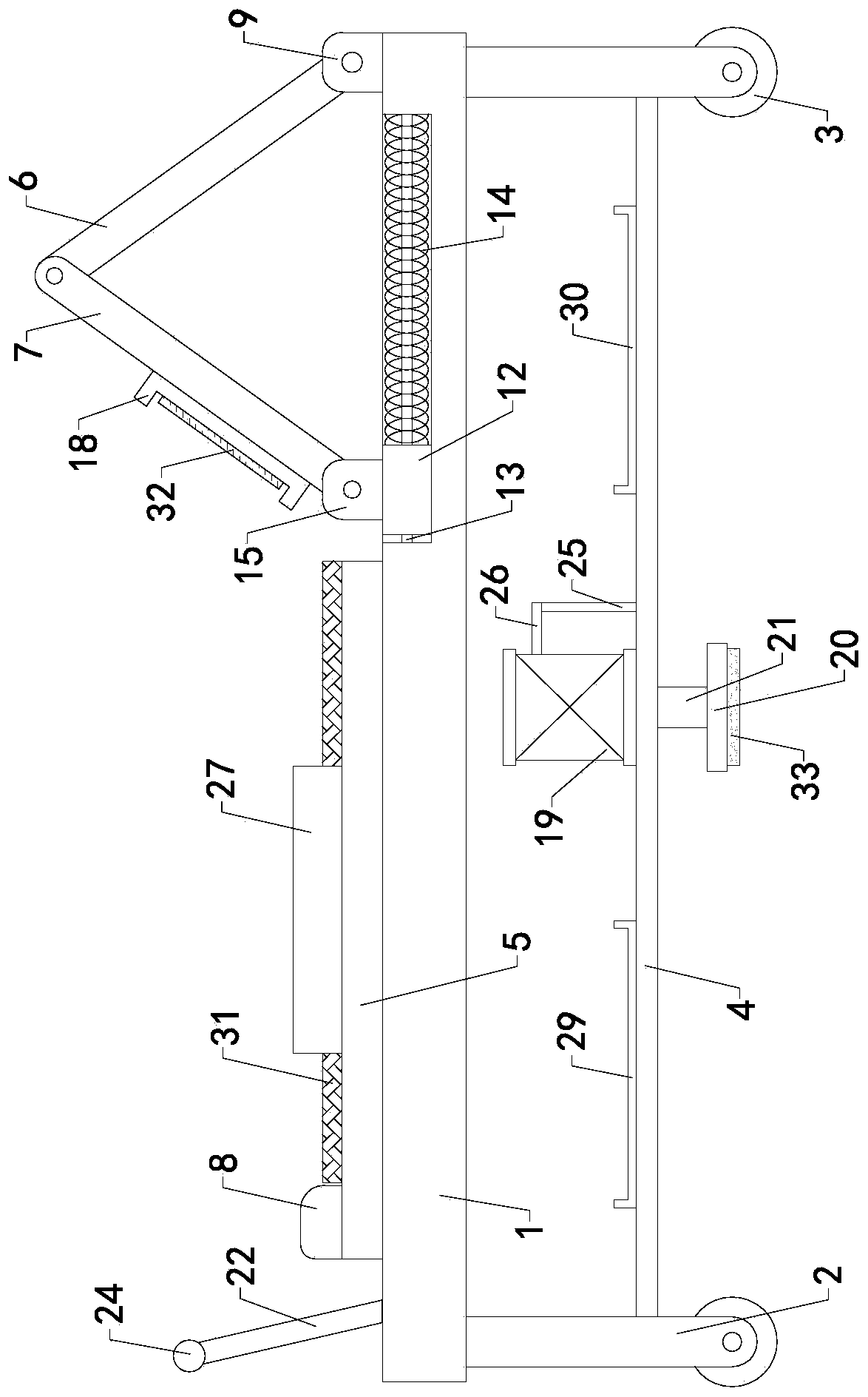
[0002] As everyone knows, the orthopedic traction device is a kind of auxiliary device used for orthopedic treatment and rehabilitation to perform leg traction exercises for patients with leg fractures, and it has been widely used in the field of medical equipment; The traction device includes a base plate, four sets of legs, four sets of rollers, a horizontal plate, a placement plate, a fixed plate and a buffer plate, and the tops of the four sets of outriggers are respectively connected to the left front, right front, left rear and right rear of the bottom of the base , the four sets of rollers are respectively rotatably installed at the bottom of the four sets of outriggers, the horizontal plate is horizontally installed between the four sets of outriggers, the bottom of the placing plate is connected to the left half of the top of the bottom plate, and the left half of the top of the placing plate is provided with a headrest , the bottom end of the fixed plate is connected with the right half of the top of the base plate, the left end of the fixed plate is provided with an elastic mechanism, and the left end of the elastic mechanism is connected with the right end of the buffer plate; when the existing orthopedic traction device is used, the patient lies flat on the placement plate, with the head Pillow on the headrest, step on the buffer plate with both feet, push the buffer plate to move to the right with both feet, and then relax, the buffer plate moves to the left under the action of the elastic mechanism, and then the patient pushes the buffer plate to the right again, repeating the above operations, It is possible to carry out traction exercise on the patient's leg to restore strength to the leg; in the use of the existing orthopedic traction device, it is found that when the buffer plate moves to the left to the end point, the patient's leg is in a bent state, and at this time the patient's The heels of the feet will be out of contact with the buffer plate, resulting in poor comfort; when the device is in use, the position is prone to shift, resulting in poor reliability

Method used


Image

  • Orthopedic traction device
  • Orthopedic traction device
  • Orthopedic traction device

Examples


Embodiment Construction

[0019] The specific implementation manners of the present invention will be further described in detail below in conjunction with the accompanying drawings and embodiments. The following examples are used to illustrate the present invention, but are not intended to limit the scope of the present invention.

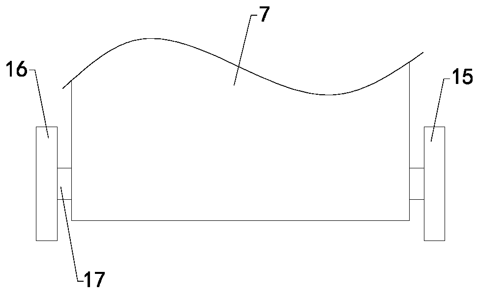
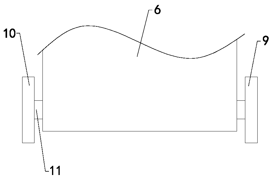
[0020] Such as Figure 1 to Figure 5 As shown, a traction device for orthopedics of the present invention includes a bottom plate 1, four sets of legs 2, four sets of rollers 3, a horizontal plate 4, a placement plate 5, a fixing plate 6 and a buffer plate 7, and the tops of four sets of legs 2 They are respectively connected to the left front side, the right front side, the left rear side and the right rear side of the bottom of the bottom plate 1, the four sets of rollers 3 are respectively rotatably installed on the bottom ends of the four sets of legs 2, and the horizontal plate 4 is installed horizontally between the four sets of legs 2 Between, the bottom of the pla...


PUM


Abstract

The invention relates to the technical field of medical equipment accessory devices, in particular to an orthopedic traction device. The traction device can keep both feet of a patient still attachedto a buffer plate when legs of the patient are in a bent state, and the device can be positioned. The traction device comprises a bottom plate, four groups of support legs, four groups of rollers, a transverse plate, a placement plate, a fixing plate and the buffer plate, wherein a headrest is arranged in a left-half area of the top end of the placement plate; the traction device also comprises afront support plate, a back support plate, a fixed shaft, a sliding plate, a limiting rod, a spring, a front connecting plate, a back connecting plate, a connecting shaft and a pedal, a fixing hole isformed in the lower-half area of the front side wall of the fixing plate, a through hole is formed in the lower-half area of the front side wall of the buffer plate, and a clamping groove is formed in the central area of the left side wall of the pedal; and the traction device also comprises an air cylinder and a braking plate, a telescopic hole is longitudinally formed in the central area of thetop end of the transverse plate, and a telescopic rod is arranged at an output end of the bottom of the air cylinder.

Description

technical field [0001] The invention relates to the technical field of medical equipment attachments, in particular to an orthopedic traction device. Background technique [0002] As everyone knows, the orthopedic traction device is a kind of auxiliary device used for orthopedic treatment and rehabilitation to perform leg traction exercises for patients with leg fractures, and it has been widely used in the field of medical equipment; The traction device includes a base plate, four sets of legs, four sets of rollers, a horizontal plate, a placement plate, a fixed plate and a buffer plate, and the tops of the four sets of outriggers are respectively connected to the left front, right front, left rear and right rear of the bottom of the base , the four sets of rollers are respectively rotatably installed at the bottom of the four sets of outriggers, the horizontal plate is horizontally installed between the four sets of outriggers, the bottom of the placing plate is connected ...

Claims


Application Information

Patent Timeline
IPC IPC(8): A61H1/02
CPCA61H1/0222A61H1/0237A61H2201/0142A61H2201/1261A61H2201/1607A61H2201/1642
Inventor 韩易元秦宏平
Owner 泰信利美信息科技(常州)有限公司
Learn More